
Under-ice detection system based on capture remotely-operated vehicle (ROV) and suitable for ice hole laying and recovery

A detection system and ice hole technology, which is applied in underwater operation equipment, transportation and packaging, ships, etc., can solve the problems of limited endurance of AUV, limited detection time and range, and inability to deploy and recover, so as to improve propulsion efficiency. , Improve the detection range and reduce the effect of forward resistance

Active Publication Date: 2019-07-26
HANGZHOU DIANZI UNIV
View PDF7 Cites 7 Cited by
  • Summary
  • Abstract
  • Description
  • Claims
  • Application Information

AI Technical Summary

Problems solved by technology

In this way, AUVs are usually deployed and recovered by digging through the ice layer and then deploying and recovering them in larger ice holes. However, the AUV's endurance is limited, resulting in limited detection time and range. In addition, thin ice layers can be used to open ice holes. However, for thick ice layers, such as ice shelves with a thickness of thousands of meters in the Antarctic region, holes are usually drilled by polar hot water drilling rigs, and the diameter of the opened ice holes is usually limited (in the order of 35cm to 80cm) , so it is impossible to directly deploy and recover AUVs in deep and narrow ice holes
[0003] Existing under-ice detection robots, such as a kind of under-ice detection robot published in patent number 201710886568.1, and a kind of under-ice detection robot published in patent number 201810313651.4, can only be detected by cutting through the ice layer and then AUVs are deployed and recovered in ice holes to achieve under-ice detection, and AUVs cannot be deployed and recovered directly in deep and narrow ice holes

Method used


Image

  • Under-ice detection system based on capture remotely-operated vehicle (ROV) and suitable for ice hole laying and recovery
  • Under-ice detection system based on capture remotely-operated vehicle (ROV) and suitable for ice hole laying and recovery
  • Under-ice detection system based on capture remotely-operated vehicle (ROV) and suitable for ice hole laying and recovery

Examples


Embodiment 1

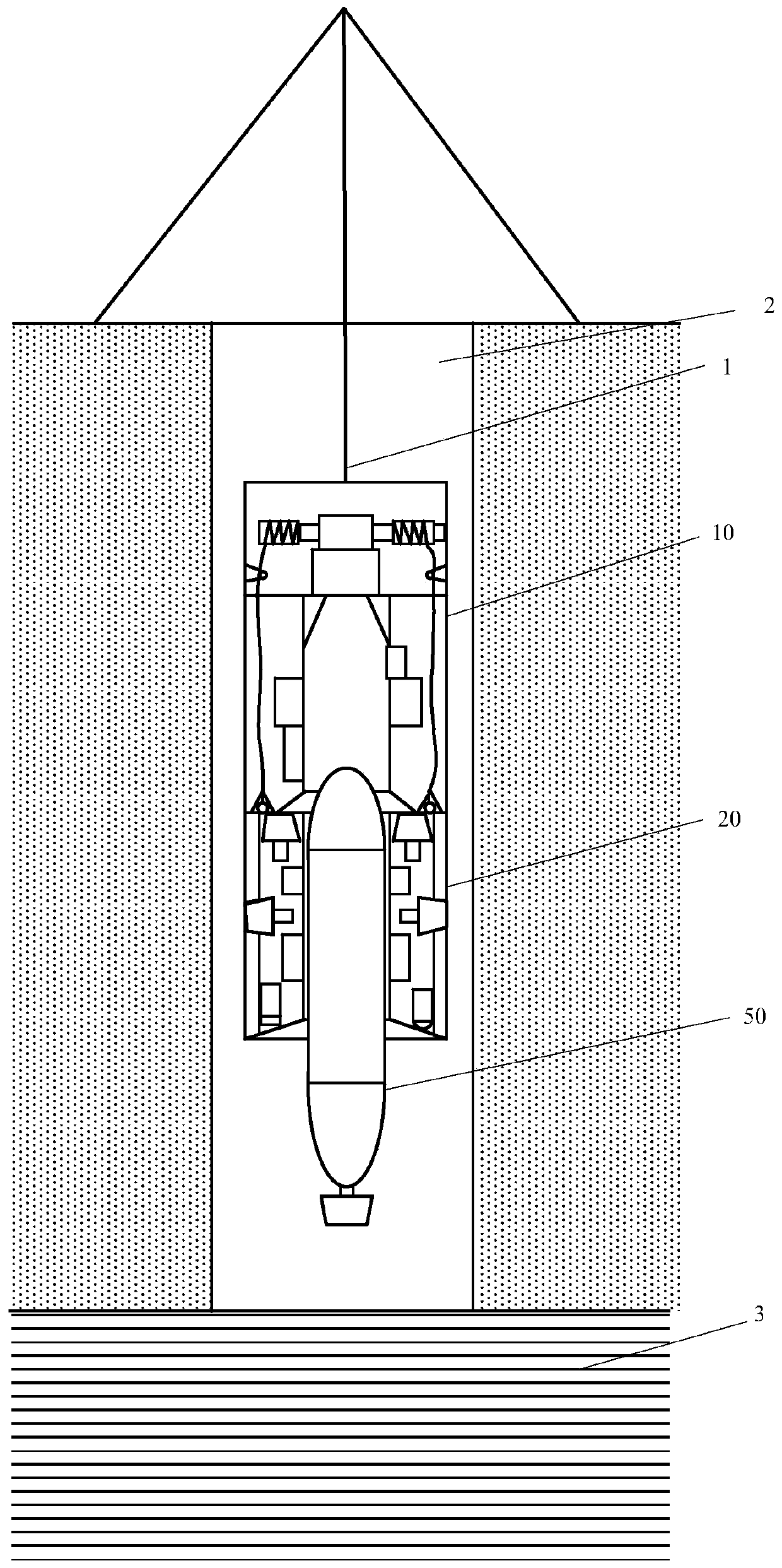
[0038] see figure 1 , this embodiment provides an under-ice detection system based on capturing ROVs suitable for deployment and recovery of ice holes, which can enter the water 3 through ice holes 2 with limited aperture, including

[0039] The load-bearing cable 1 is used to hang in the ice hole 2 to lift and lower the under-ice detection system;

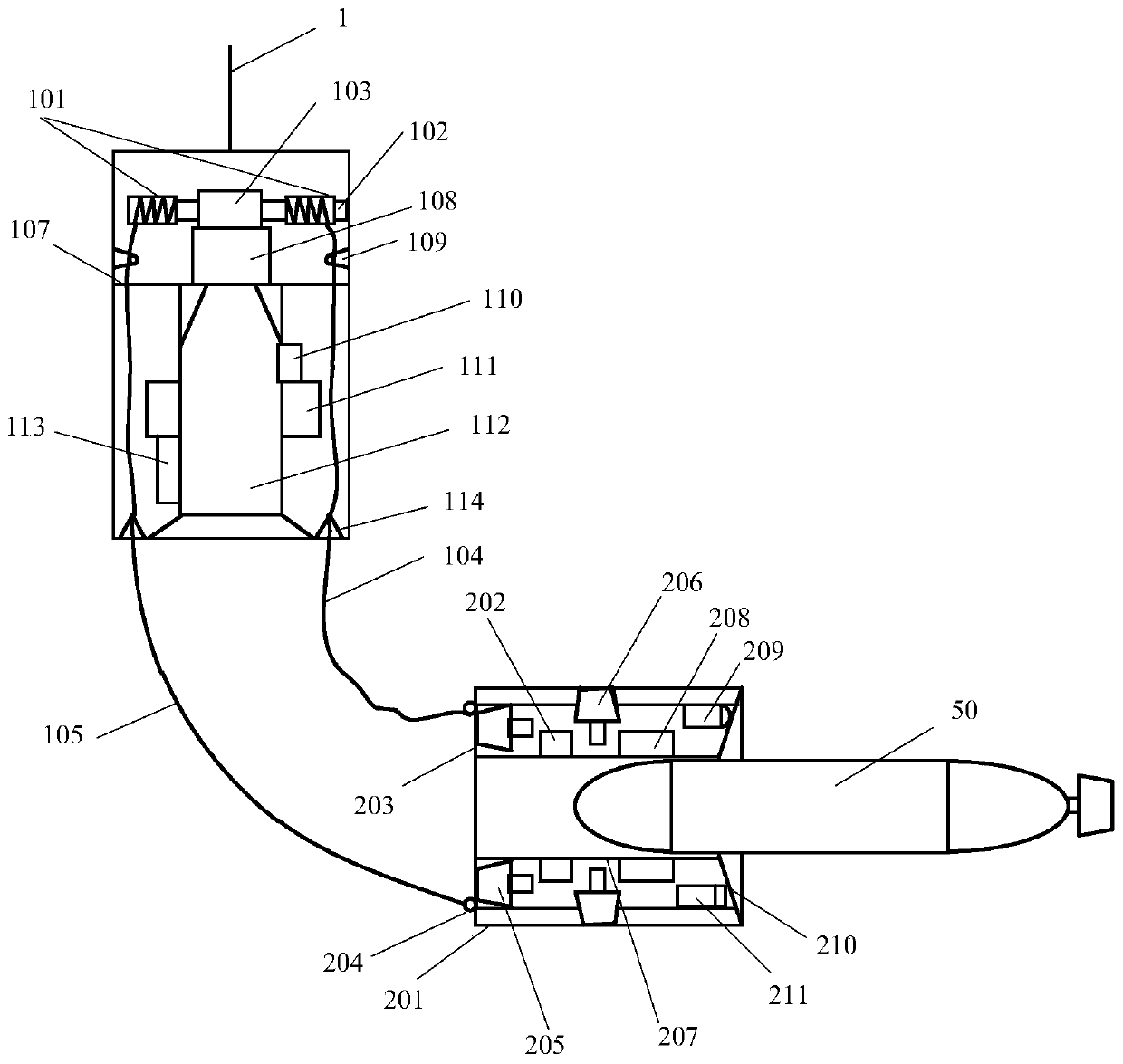
[0040] The connection cabin 10 is fixedly connected with the load-bearing cable 1 that drives it to move, and is used to capture the underwater retraction of ROV20 (Remotely Operated Vehicle, cable-controlled submersible) and the charging endurance and data communication of the AUV for underwater ice detection;

[0041] Catch the ROV20, connect with the connection cabin 10 to form a cylindrical overall structure that can move in the ice hole 2 with limited aperture, and can break away from the connection cabin 10 for water sample or sediment collection when the water 3 is submerged. It can actively capture and connect with the un...

Embodiment 2

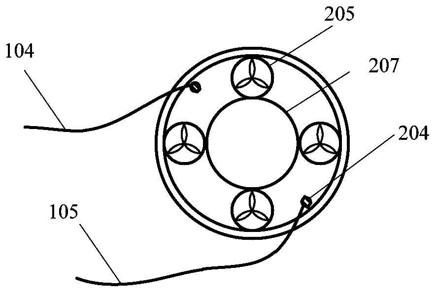
[0063] see Figure 6 The difference between the present embodiment and the first embodiment is that the capture ROV20 in this embodiment is not equipped with a lateral thruster 206, so that the maneuverability of the capture ROV20 will be slightly worse, but the advantage is that the axial length of the capture ROV20 can be reduced. And at the position where the ROV outer cylinder 201 is close to the backward thruster 205, large circular holes 216 are respectively dug, the purpose is to make the external water flow better communicate with the backward thruster and improve the propulsion efficiency.

[0064] The rest of the structures and functions are the same as those in Embodiment 1.


PUM


Abstract

The invention discloses an under-ice detection system based on a capture remotely-operated vehicle (ROV) and suitable for ice hole laying and recovery. The under-ice detection system can enter water through an ice hole with the limited hole diameter, and comprises a load-bearing cable, a connecting bin, the capture ROV and an under-ice detection autonomous underwater vehicle (AUV); the load-bearing cable is used for being hung in the ice hole to lift upwards and lower the under-ice detection system; the connecting bin is fixedly connected with the load-bearing cable driving the connecting binto move, and used for underwater collecting and expanding of the capture ROV and charging endurance and data communication of the under-ice detection AUV; the capture ROV is connected with the connecting bin to be combined into a cylindrical overall structure capable of moving in the ice hole with the limited hole diameter, and can be disengaged from the connecting bin underwater to collect a water sample or sediment and connect the under-ice detection AUV; and the under-ice detection AUV is used for being disengaged from the capture ROV underwater to conduct underwater detection or being connected and fixed into the capture ROV to be movably recovered into the connecting bin along with the capture ROV for charging endurance and data communication. The under-ice detection system does not collide with the wall face of the ice hole, thus parts are not damaged, the detection time of the system under ice is prolonged, the detection range of the system under the ice is enlarged, and the detection efficiency is improved.

Description

technical field [0001] The invention belongs to the field of ocean technology and engineering, and relates to an under-ice detection system based on capturing ROVs and suitable for laying and recovering ice holes. Background technique [0002] At the Earth's poles there are ice packs and ice shelves that connect the oceans to the polar ice caps. The detection and sampling of the subglacial environment, including subglacial ocean thermohaline circulation observation, subglacial marine ecological environment detection, subglacial seawater and sediment sampling, etc. Important means, has important scientific significance. At present, there are mainly two ways to detect the sub-ice environment. One is to drill holes on the ice surface and put the instruments and equipment with cables into them. The instruments and equipment deployed in this way are limited to the detection of very limited areas under the ice holes. range, it is impossible to conduct large-scale detection under...

Claims


Application Information

Patent Timeline
Patent Type & Authority Applications(China)
IPC IPC(8): B63C11/34B63C11/52
CPCB63C11/34B63C11/52
Inventor 彭时林蔡文郁于海滨史剑光刘敬彪
Owner HANGZHOU DIANZI UNIV
Learn More