Packaging device for automobile part packaging bag

A technology for auto parts and packaging devices, applied in packaging sealing/fastening, packaging, transportation packaging, etc., can solve the problems of complex operation of sealing devices, waste of labor, and inability to achieve integrated sealing and shearing operations.

Inactive Publication Date: 2019-07-26
三七知明(北京)科技有限公司
View PDF6 Cites 0 Cited by
  • Summary
  • Abstract
  • Description
  • Claims
  • Application Information

AI Technical Summary

Problems solved by technology

[0003] In the automobile manufacturing industry, due to the small size of the parts on the car, they are easy to be lost or polluted during the long-term transportation and storage, so it is necessary to use professional matching plastic bags to classify some specific tiny parts Storage and packaging, due to the different sizes and specifications of auto parts, the traditional assembly line sealing and packaging device is not suitable for this kind of plastic packaging bag sealing work, and professional operators are required to manually perform the sealing operation. The traditional sealing device is complicated to operate. When the packaging bag is sealed, it is impossible to achieve the integrated operation of sealing and cutting. Users often need to process multiple times to meet the quality requirements of product export. The labor intensity is high and the distribution of labor is uneven, which greatly wastes the labor of personnel. degree, reducing the efficiency of product production;

Method used


Image

  • Packaging device for automobile part packaging bag
  • Packaging device for automobile part packaging bag
  • Packaging device for automobile part packaging bag

Examples


Embodiment Construction

[0035] The technical solutions in the embodiments of the present invention will be clearly and completely described below in conjunction with the accompanying drawings in the embodiments of the present invention. Apparently, the described embodiments are only some, not all, embodiments of the present invention. Based on the embodiments of the present invention, all other embodiments obtained by persons of ordinary skill in the art without making creative efforts belong to the protection scope of the present invention.

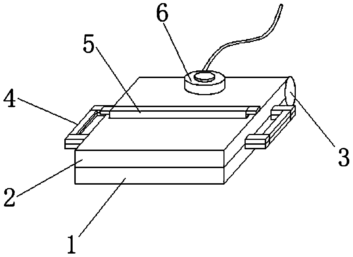
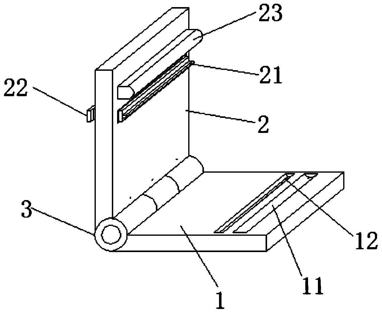
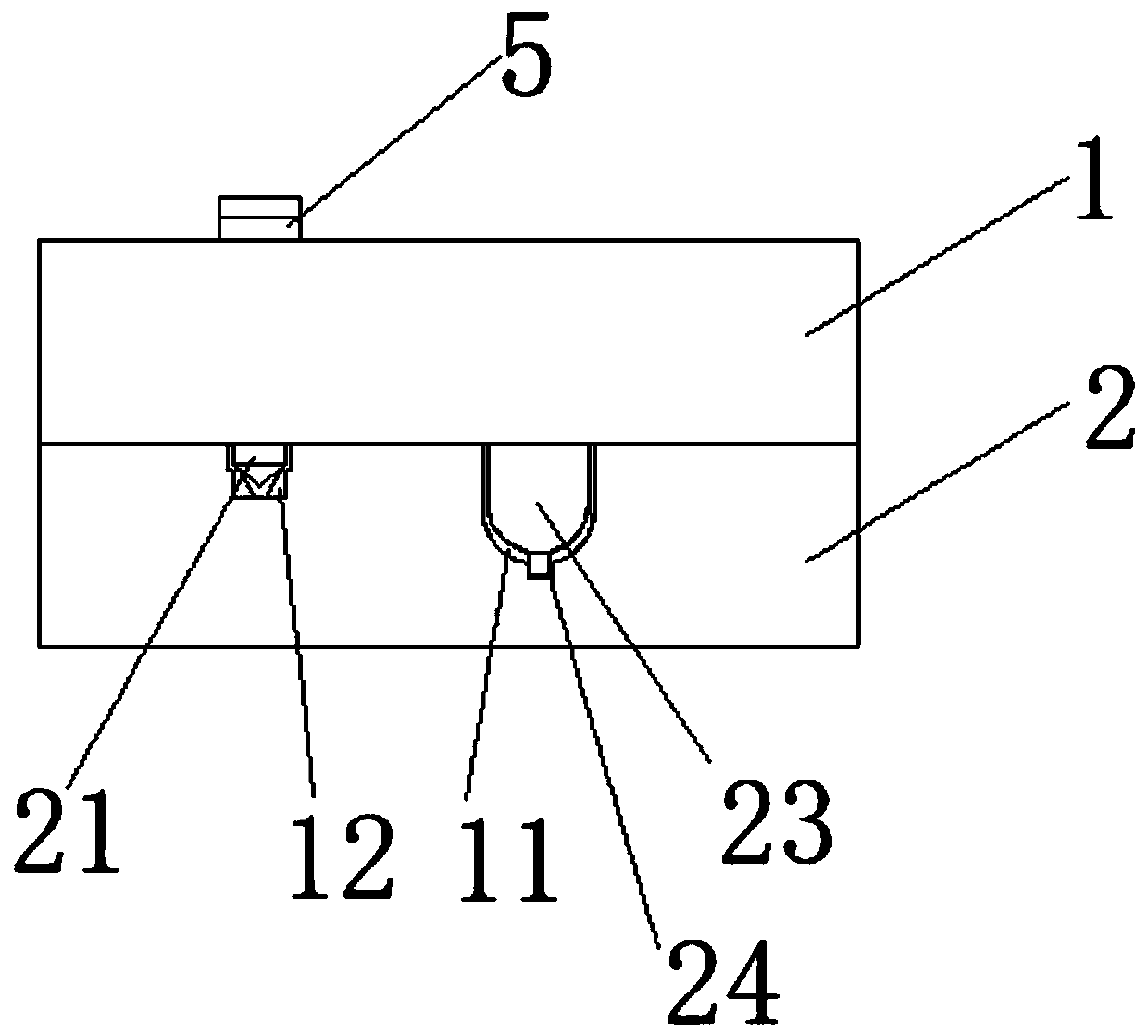
[0036] see Figure 1-6 , the present invention provides a technical solution:

[0037] Such as figure 1 and Image 6 As shown, a packaging device for auto parts packaging bags includes a lower pressing plate 1, an upper outer surface of the upper end of the lower pressing plate 1 is provided with an upper pressing plate 2, and the rear outer surface of the upper pressing plate 2 and the lower pressing plate 1 is provided with a hinge joint. shaft 3, the insi...


PUM

PropertyMeasurementUnit
Stiffness coefficientaaaaaaaaaa

Abstract

The invention discloses a packaging device for an automobile part packaging bag. The packaging device comprises a lower pressing plate, wherein a hinging shaft is arranged on outer surfaces of rear ends of an upper pressing plate and the lower pressing plate; a torsion spring is arranged in the hinging shaft; a first pressing plate and a controller are arranged on the outer surface of the upper end of the upper pressing plate; the controller is located behind the first pressing plate; second pressing plates are fixedly connected with the outer surfaces of two sides of the first pressing plate;handles are fixedly connected with the outer surfaces of one side of the upper pressing plate and one side of the lower pressing plate; and the first pressing plate penetrates through the upper pressing plate and extends to the outer surface of the lower end of the upper pressing plate. According to the packaging device disclosed by the invention, a ceramic pressed sheet and a pressing groove aretightly laminated with a hot-melting plastic bag sealing opening in a specific operation process, the sealing opening is flat and tight and a condition that the sealing effect is relatively poor whena bubble phenomenon occurs is avoided; and in a sealing process, a user can utilize a first blade and a first auxiliary tooth groove to laminate, so that surplus parts are cut off and the sealing efficiency of the device is effectively improved.

Description

technical field [0001] The invention relates to the technical field of sealing devices, in particular to a packaging device for packaging bags of auto parts. Background technique [0002] Plastic bag is a bag made of plastic (polyethylene, polypropylene, polyester, nylon, etc.) as the main raw material. It is an indispensable item in people's daily life. The advantages of extremely light, large capacity, and easy storage are widely used. Compared with the Chinese patent of a plastic bag rapid heating and sealing device CN201610524735.3, its advantage is that the controller is opened first, and the device starts to work normally, and the battery in the rectangular box can last To store electricity, the rectangular box on the upper surface of the rectangular base is used to carry devices such as slide rails. The electric control trolley on the upper surface of the rectangular box horizontally placed on the upper surface of the slide rail starts to move, driving the pressure se...

Claims


Application Information

Patent Timeline
IPC IPC(8): B65B51/10B65B61/06
CPCB65B51/10B65B61/06
Inventor 李强
Owner 三七知明(北京)科技有限公司
Why Eureka
Try Eureka