LED fluorescence emission spectrum-based surface temperature measurement method

A surface temperature and measurement method technology, which is applied to thermometers, thermometers, and measuring devices with physical/chemical changes, can solve problems such as difficult temperature measurement and poor surface flatness of white light LEDs, and achieve wide application, good consistency, and avoid The effect of man-made damage

Active Publication Date: 2019-07-26
XIAMEN UNIV
View PDF6 Cites 4 Cited by
  • Summary
  • Abstract
  • Description
  • Claims
  • Application Information

AI Technical Summary

Problems solved by technology

However, due to the poor surface flatness of white LEDs coated with a mixture of fluorescent materials and transparent silica gel on the chip surface, it is difficult to achieve accurate temperature measurement using infrared thermal imaging, and how to accurately determine the emissivity value is also a key problem and difficulty

Method used


Image

  • LED fluorescence emission spectrum-based surface temperature measurement method
  • LED fluorescence emission spectrum-based surface temperature measurement method
  • LED fluorescence emission spectrum-based surface temperature measurement method

Examples


Embodiment 1

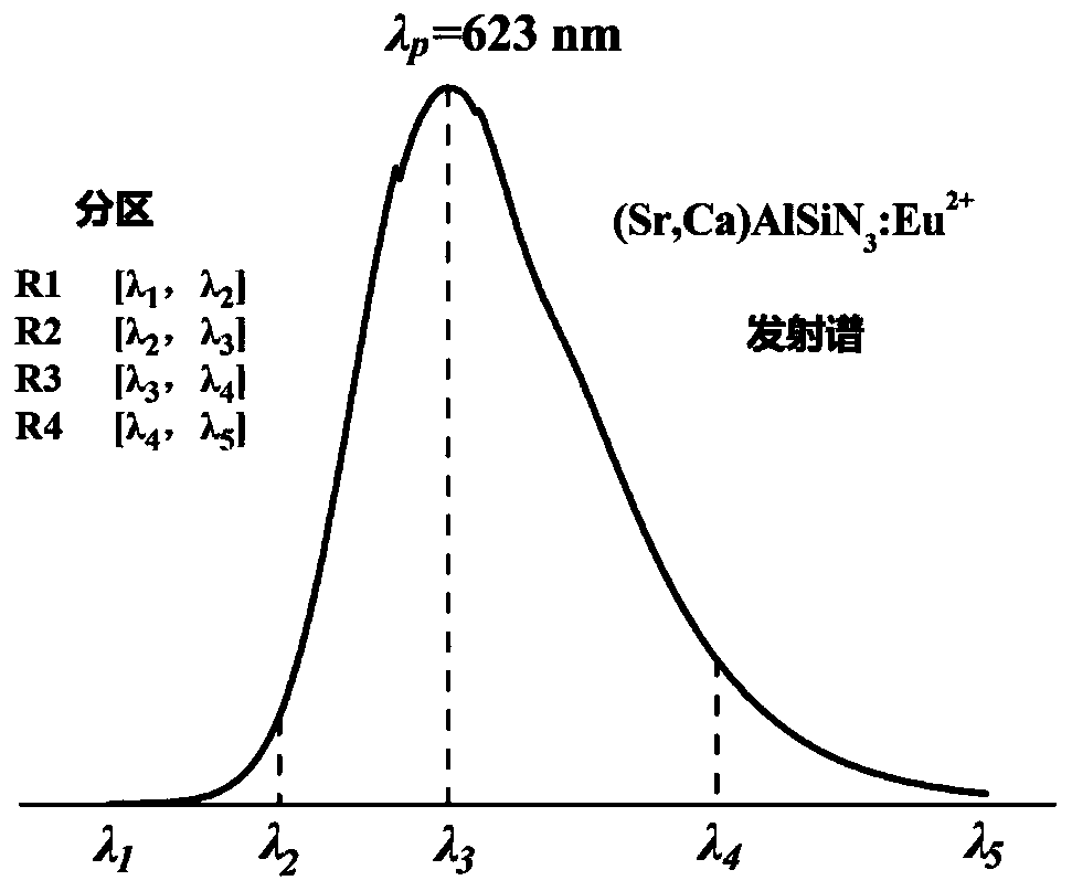
[0047] (1) Fix the LED sample 1 to be tested on the temperature control table, and then connect a constant current source to power the LED sample 1 to be tested; wherein, in the LED sample 1, the fluorescent material is (Si, Ca)AlSiN 3 :Eu 2+ A mixture of red fluorescent powder and silica gel at a mass ratio of 1:4.

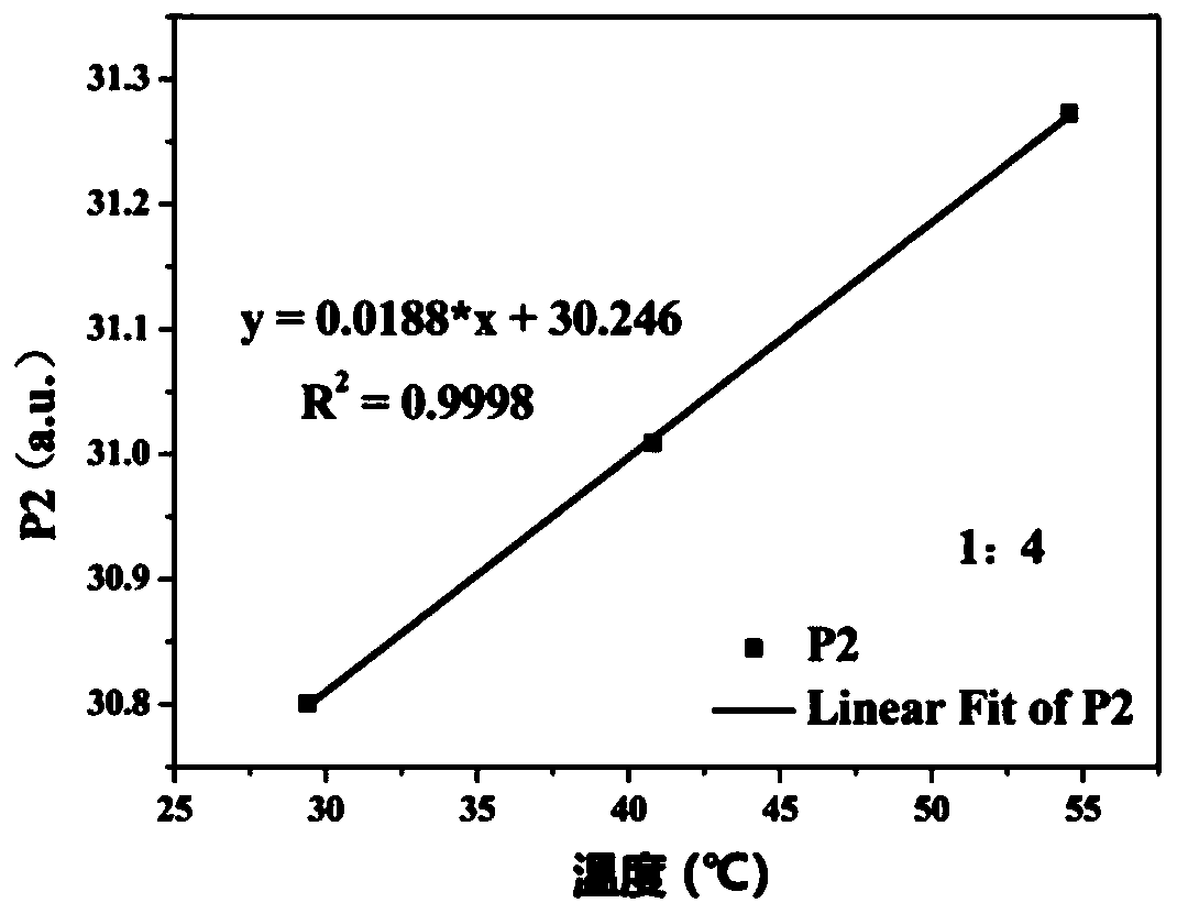
[0048] (2) Select an appropriate small current of 10mA to light up the LED sample 1 to be tested, and then select a set of suitable temperatures T0=30°C, T1=45°C, T2=60°C (generally lower than the failure temperature of the LED sample to be tested , the failure temperature of LED sample 1 in this embodiment is about 140°C), the respective spectra of fluorescent materials at T0, T1, and T2 temperatures are collected by a spectrometer, and the P2 value of the emission spectrum of the fluorescent material is calculated, and finally T0, T1, The functional relationship between T2 and P2, such as image 3 Shown is the calibration curve fitted by P2.

[0049] (3) Adj...

Embodiment 2

[0054] The test method and conditions of Example 2 are the same as those of Example 1, the difference is that in the LED sample 2 to be tested, the fluorescent material is (Si, Ca)AlSiN 3 :Eu 2+ A mixture of red fluorescent powder and silica gel at a mass ratio of 1:5.

[0055] Figure 4 It is the calibration curve fitted by P2; Table 2 is the comparison result of the calculated fitting temperature Tc and the thermocouple temperature Tt.

[0056]

[0057] Table 2

Embodiment 3

[0059] The test method and conditions of Example 3 are the same as those of Example 1, the difference is that in the LED sample 3 to be tested, the fluorescent material is (Si, Ca)AlSiN 3 :Eu 2+ A mixture of red fluorescent powder and silica gel at a mass ratio of 1:10.

[0060] Figure 5 It is the calibration curve fitted by P2; Table 3 is the comparison result of the calculated fitting temperature Tc and the thermocouple temperature Tt.

[0061]

[0062] table 3

[0063] Through the data results of the above examples, it can be seen that the temperature difference between the temperature of LED sample 1, LED sample 2 and LED sample 3 under five different currents and the temperature of the micro-thermocouple is within 5°C, showing good Consistency, further illustrates the feasibility of the method of the present invention, the temperature difference may be partly derived from thermocouple light absorption.

[0064] The method of the present invention is applicable to ...


PUM


Abstract

The invention discloses an LED fluorescence emission spectrum-based surface temperature measurement method, and relates to the field of light emitting diode surface temperature measurement methods. The method comprises the following steps of (1) carrying out region division on a normalized emission spectrum of a fluorescent material and integrating each region, wherein the obtained fluorescent material transmitting power is recorded as Pe; (2) testing the current influence degree of the transmitting power Pe of each integral region, and selecting the integral region with the minimum current influence degree as a detection region; (3) taking 1-3% of a rated current value as small current to supply power to an LED sample, acquiring the emission spectrum of the fluorescent material by using aspectrograph, and establishing a linear relationship between the transmitting power Pe of the detection region and the temperature T of the emission spectrum; and (4) under the practical working state of the LED sample, substituting the transmitting power Pe value of the detection region into a relational expression of Pe and T so as to obtain the surface temperature of the fluorescent material.According to the method, a non-contact method is adopted to measure the surface temperatures of fluorescent materials, so that the influences of LED device packaging are avoided and the reliability ishigh.

Description

technical field [0001] The invention relates to the field of measuring methods for the surface temperature of light-emitting diodes, in particular to a method for measuring the surface temperature based on LED fluorescence emission spectrum. Background technique [0002] Compared with traditional artificial lighting sources such as incandescent lamps and fluorescent lamps, phosphor-coated white light-emitting diodes (pc-WLEDs) converted from fluorescent materials have many advantages such as high luminous efficiency, low power consumption, long life and environmental friendliness. Advantages, it has been widely promoted and applied in fields including home lighting, commercial lighting, visible light communication, agricultural lighting, automotive headlights and biomedicine. At present, the fluorescent conversion materials used in white light illumination mainly include YAG:Ce 3+ Phosphor powders represented by rare earth materials or quantum dot conversion materials repre...

Claims


Application Information

Patent Timeline
IPC IPC(8): G01K11/32
CPCG01K11/3213
Inventor 郭自泉林苡杨宸吕毅军高玉琳朱丽虹陈国龙阮育娇康品春林岳王冬陈忠
Owner XIAMEN UNIV
Why Eureka
Try Eureka