A pipe-connected steam heat exchanger

A heat exchanger and steam technology, applied in indirect heat exchangers, heat exchanger types, heat exchanger shells, etc., can solve problems such as affecting heat exchange efficiency and reducing heat exchange capacity.

Active Publication Date: 2020-10-30
YANTAI MOON HEAT EXCHANGE TECH
View PDF7 Cites 0 Cited by
  • Summary
  • Abstract
  • Description
  • Claims
  • Application Information

AI Technical Summary

Problems solved by technology

During the evaporation process of the heat exchange tube, liquid will inevitably be carried into the steam tube. At the same time, due to the exothermic condensation at the condensation end, there will be liquid in the condensation end, and the liquid will inevitably enter the steam tube, so that the fluid in the heat exchange tube will It is a vapor-liquid mixture. The existence of a vapor-liquid mixture causes the gas to mix together, and the heat transfer capacity between the gas and the liquid decreases, which greatly affects the heat transfer efficiency.

Method used


Image

  • A pipe-connected steam heat exchanger
  • A pipe-connected steam heat exchanger
  • A pipe-connected steam heat exchanger

Examples


Embodiment Construction

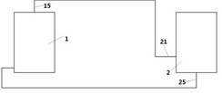
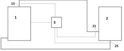
[0049] An evaporator system includes an evaporator 1 and a steam utilization device 2 . The steam generated by heating in the evaporator 1 enters the steam utilization device 2 through the steam inlet pipe 21 , and is circulated to the evaporator 1 for heating after being fully heat-exchanged and utilized in the steam utilization device.

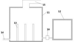
[0050] The evaporator structure is as figure 1 As shown, it includes a steam chamber 11, a water replenishment tank 12, and a water pump 16. The water replenishment tank 12 is connected to the water pump 16 through a pipeline, and the water pump 16 is connected to the steam chamber 11 through a pipeline. An electric heating device 13 is arranged in the steam chamber 11. , the upper part of the steam chamber 11 is provided with a steam outlet pipeline 15 , and the steam chamber 11 is provided with a water inlet pipeline 14 .

[0051] The water enters the steam chamber 11 from the supplementary water tank 12 through the water pump 16 , and is...


PUM


Abstract

The invention provides a vapor heat exchanger. The vapor heat exchanger comprises a collecting box and steam tubes, wherein the steam tubes upwards extend from the collecting box; a steam inlet and acondensed water outlet are formed in the collecting box; steam enters the collecting box, and upwards flows from the collecting box to enter the steam tubes; the steam tubes perform heat exchange withoutside to form condensed water; condensed water returns into the collecting box under action of the gravity, and flows out from a water return hole in the lower part of the collecting box; a communication tube is arranged between at least two adjacent steam tubes of the multiple steam tubes; multiple communication tubes are arranged between adjacent steam tubes from the lower parts of the steamtubes to the upper parts of the steam tubes; and the diameters of the communication tubes are continuously increased from the lower parts of the steam tubes to the upper parts of the steam tubes. Along with upward flow of fluid, fluid continuously releases heat, and released heat in different heat collecting tubes becomes more and more uniform, and therefore, pressure balance can be guaranteed tobe reached as quickly as possible in a fluid flowing process.

Description

technical field [0001] The invention relates to the fields of boiler technology and heat exchangers, in particular to an intelligently controlled evaporator and a steam heat exchanger thereof. Background technique [0002] An evaporator is a mechanical device that uses heat from fuel or other energy sources to heat water into steam. The evaporator has a wide range of applications, and is widely used in garment factories, dry cleaners, restaurants, steamed bun shops, canteens, restaurants, factories and mines, bean products factories and other places. The steam generation system includes an evaporator, and the steam generated by the evaporator is generally used in a steam utilization device, but there is a lack of corresponding intelligent control adjustment between the steam utilization device and the evaporator, such as controlling the steam generation of the evaporator according to the conditions of the steam utilization equipment. Therefore, the present invention mainly ...

Claims


Application Information

Patent Timeline
Patent Type & Authority Patents(China)
IPC IPC(8): F22B1/28F22B35/00F22B37/10F28D7/16F28F9/22
CPCF22B1/284F22B35/00F22B37/10F28D7/163F28F9/22
Inventor 胡全君马军江程李言伟赵伟
Owner YANTAI MOON HEAT EXCHANGE TECH
Why Eureka
Try Eureka