Liquid sensor, and preparation method and application thereof
A technology of liquid sensor and graphene paper, applied in the direction of material resistance, etc., can solve the problem of inability to detect liquid
- Summary
- Abstract
- Description
- Claims
- Application Information
AI Technical Summary
Problems solved by technology
Method used
Image
Examples
preparation example Construction
[0037] The present invention also provides a method for preparing the liquid sensor described in the above technical solution, comprising the following steps:
[0038] Laser irradiation is performed on both sides of the polyimide paper to obtain graphene paper;
[0039] Coating silver paste on opposite ends of the graphene paper, forming a silver coating after drying, and obtaining a liquid sensor.
[0040] The invention irradiates the two sides of the polyimide paper with laser to obtain the graphene paper. In the present invention, the polyimide (PI) paper is a commercially available product well known to those skilled in the art, and the size of the polyimide paper is preferably 10 cm×10 cm.
[0041] In the present invention, the laser irradiation is preferably carbon dioxide laser, the wavelength is preferably 9.3-12 μm, more preferably 9.5-11.5 μm; the irradiation method is preferably a fill-scan mode; the image density of the laser irradiation is preferably 100-1000PPI,...
Embodiment 1
[0052] Polyimide (PI) paper was purchased commercially. Equipped with CO with a wavelength of 10.6 μm 2 The laser irradiation system of the laser (DLS 2.3, Universal Laser Systems, Inc) adopts the filling and scanning mode irradiation, and the laser irradiation parameters are: the image density is fixed at 500PPI, the scanning rate is 7inch / s, and the area of PI paper for one scan is 10×10cm 2 , single-sided scanning time is 8min, single-sided 100cm 2 The total preparation time of LIGP was 16min, the scanning power was 10W, and the scanning parameters on both sides were the same.
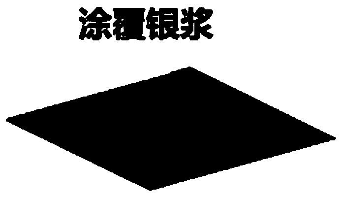
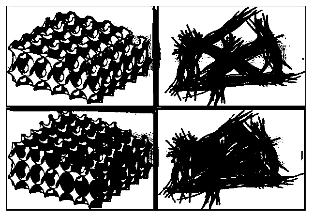
[0053] Gained graphene paper is cut into the sample of 1cm * 1cm, is coated with silver paste layer at two opposite sides, and the formation width is 0.1mm, and length is the silver coating of 1cm, obtains as figure 1 The liquid sensor shown. Add the organic solvent dropwise on the graphene paper, using figure 2 Indicates the schematic diagram of infiltration: figure 2 The upper picture is ...
Embodiment 2~5
[0055] Prepare graphene paper in the manner of Example 1, the difference is that the power is different, the power of Example 2 is 11W, the power of Example 3 is 12W, Example 4 is 13W, and Example 5 is 15W.
[0056] Taking the obtained graphene paper of embodiment 1, embodiment 3 and embodiment 5 as example, the SEM characterization of the obtained graphene paper is carried out, to study the change situation of the microstructure of the obtained graphene paper under different powers, the characterization result is as follows image 3 shown. image 3 Among them, from left to right are the SEM pictures of the graphene paper obtained in embodiment 1, embodiment 3 and embodiment 5 respectively, as can be seen from the figure, with the increase of power, the microstructure of graphene paper changes from more small hole structure Gradually transform to mesoporous knots, and then transform to macroporous structures composed of fibers, which directly affects the specific surface area ...
PUM
| Property | Measurement | Unit |
|---|---|---|
| Specific surface area | aaaaa | aaaaa |
| Thickness | aaaaa | aaaaa |
| Width | aaaaa | aaaaa |
Abstract
Description
Claims
Application Information
 - R&D
- Intellectual Property
- Life Sciences
- Materials
- Tech Scout
- Unparalleled Data Quality
- Higher Quality Content
- 60% Fewer Hallucinations
Browse by: Latest US Patents, China's latest patents, Technical Efficacy Thesaurus, Application Domain, Technology Topic, Popular Technical Reports.
© 2025 PatSnap. All rights reserved.Legal|Privacy policy|Modern Slavery Act Transparency Statement|Sitemap|About US| Contact US: help@patsnap.com


