Brake release tool of motor

A technology for releasing brakes and motors with motors, applied in the field of elevators, can solve problems such as reduced braking force, and achieve the effects of reducing wear, preventing insufficient braking force, and avoiding failures.

Active Publication Date: 2019-08-02
NANTONG YAO TELEI ELEVATOR PROD CO LTD
View PDF6 Cites 0 Cited by
  • Summary
  • Abstract
  • Description
  • Claims
  • Application Information

AI Technical Summary

Problems solved by technology

At this time, when the elevator is braking, the braking force of the motor braking device is reduced due to the rust on the surface of the brake disc

Method used


Image

  • Brake release tool of motor
  • Brake release tool of motor

Examples


Embodiment 1

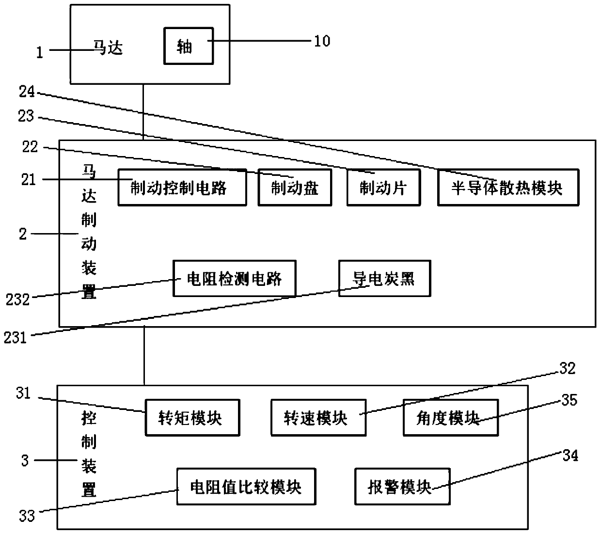
[0027] Please see figure 1 It is a structural schematic diagram of a preferred embodiment of a motor brake release tool of the present invention. A motor brake release tool includes a motor 1, a motor brake device 2, and a control device 3. The motor brake device 2 is arranged on the side of the motor 1. On the shaft 10, the control device 3 is electrically connected to the motor 1 and the motor brake device 2 respectively, and the motor brake device 2 includes a brake control circuit 21, a brake disc 22, a brake pad 23, and a semiconductor cooling module 24 , the brake control circuit 21 is connected to the control device 3, the brake disc 22 is concentrically fixed on the shaft 10 with the motor 1, and the brake control circuit 21 controls the brake pad 23 to lock and release the brake, The outer side of the brake pad 23 is provided with a semiconductor cooling module 24, and the control device 3 includes a torque module 31, a speed module 32, a resistance value comparison m...

Embodiment 2

[0038] This embodiment describes that maintenance personnel run-in the brake disc 22 and the brake pad 23 through the torque module 31 , the speed module 32 , the angle module 35 and the like.

[0039] Through the angle module 35, the rotation angle of the brake disc 22 or the motor 1 relative to the brake pad 23 is determined, and the control device 3 judges the grinding-in position of the brake disc 22 based on the rotation angle, and then controls the torque The module sets a torque smaller than the predetermined torque to lock the brake, so as to perform grinding on the unbroken position.

Embodiment 3

[0041] This embodiment describes the checking of the braking force of the motor braking device 2 by maintenance personnel.

[0042] When there is no one in the elevator car, when the brake pads 23 are engaged and the actual torque received by the torque module 31 is greater than the predetermined torque, it is determined that the braking force is reduced, and the brake needs to be run-in. The predetermined torque is the torque when the motor 1 stops rotating when the motor braking device 2 is in a brake state when the motor braking device 2 is powered off during normal operation. Moment module 31.

[0043] In this application, conductive carbon black is added to form a resistance detection circuit. Through the resistance value comparison module, it can be judged in time whether the motor is running with a brake, which can effectively reduce the wear of the brake pad and reduce the replacement frequency of parts; add conductive carbon black to form a resistance detection circui...


PUM


Abstract

The invention provides a brake release tool of a motor. The brake release tool is characterized by comprising a motor, a motor brake device and a control device. The motor braking device comprises a brake control circuit, a brake disc, a brake pad and a semiconductor heat-dissipating module. The semiconductor heat-dissipating module is arranged on the outer side of the brake pad. The control device comprises a torque module, a rotating speed module, a resistance value comparison module, an alarm module and an angle module. The brake release tool of the motor can be used for judging whether themotor operates with the brake or not and whether the motor is braked or not, can reduce wear of the brake pad effectively and can prevent danger induced by an insufficient brake sticking force. The brake pad is heat-dissipated by using the semiconductor heat-dissipating module and is prevented from losing efficiency as being damaged in a high-temperature environment, so that the service life of the bake pad is prolonged. The brake release tool can judge the opposite positions of the brake disc and the brake pad precisely, so that maintenance staff senses the state of the motor brake device more favorably. Failures can be found and adjusted immediately.

Description

technical field [0001] The invention relates to the technical field of elevators, in particular to a motor brake release tool. Background technique [0002] With the continuous development of modern elevator technology, machine-room-less elevators that are energy-saving, environmentally friendly and space-saving have become more and more popular among customers. During the use of machine-room-less elevators, once the power supply system fails or other unexpected factors occur, passengers will be trapped in the elevator, so the application of the brake release device of the elevator motor just solves this problem. During the running and stopping of the motor, whether the brake release device of the motor operates correctly is related to the safe operation of the motor. Once the motor brake release device does not operate correctly according to the requirements of the motor control device, the problem of the motor running with the brake or the motor not locked will often occu...

Claims


Application Information

Patent Timeline
Patent Type & Authority Applications(China)
IPC IPC(8): B66D5/02B66D5/14B66D5/30
CPCB66B5/024B66D5/14B66D5/30
Inventor 曹文胤曹阳张跃明毛益根程平刘小荣吕娟
Owner NANTONG YAO TELEI ELEVATOR PROD CO LTD
Why Eureka
Try Eureka