Synchronous inner-meshing double-rotor structure as well as rotor compressor and rotor engine based on synchronous inner-meshing double-rotor structure

A dual-rotor engine and rotor compressor technology, applied in the field of machinery

Pending Publication Date: 2019-08-02
张满云
View PDF9 Cites 2 Cited by
  • Summary
  • Abstract
  • Description
  • Claims
  • Application Information

AI Technical Summary

Problems solved by technology

[0004] The purpose of the present invention is to provide a synchronous internal meshing double-rotor structure and a rotor compressor ...

Method used


Image

  • Synchronous inner-meshing double-rotor structure as well as rotor compressor and rotor engine based on synchronous inner-meshing double-rotor structure
  • Synchronous inner-meshing double-rotor structure as well as rotor compressor and rotor engine based on synchronous inner-meshing double-rotor structure
  • Synchronous inner-meshing double-rotor structure as well as rotor compressor and rotor engine based on synchronous inner-meshing double-rotor structure

Examples


Embodiment 1

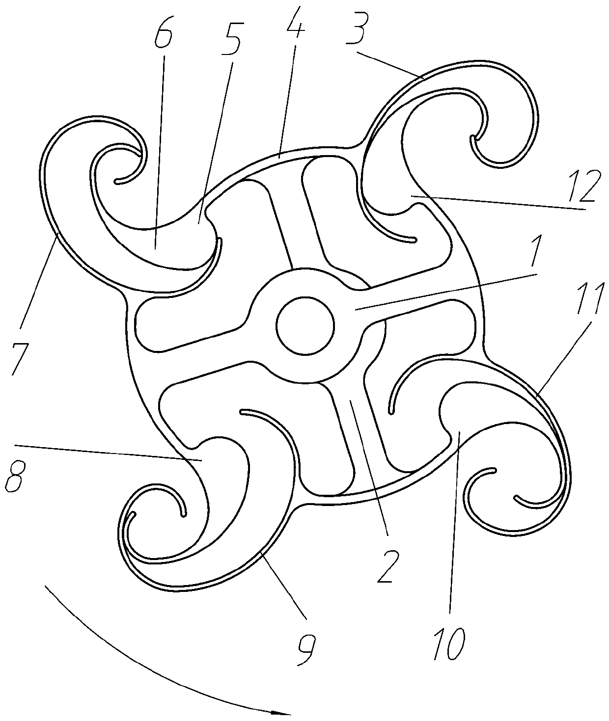
[0044] figure 1 It is a schematic diagram of the synchronous internal meshing double rotor structure of the preferred embodiment 1 of the present invention, as shown in figure 1 As shown, this embodiment provides a synchronous internal meshing double-rotor structure for a rotary compressor and a rotary engine. It includes an active rotor 1 and a passive rotor 2. The axes of the active rotor 1 and the passive rotor 2 are parallel and the axis distance d>0. The active rotor 1 and the passive rotor 2 rotate synchronously counterclockwise around their respective rotor axes.

[0045] figure 1 The synchronous internal meshing double rotor shown has a curved C-shaped plate 3, a T-shaped plate 5 composed of a separator 4 connected to a core plate 6 at one end, and the other end of the separator 4 of the T-shaped plate 5 is connected to a C-shaped On the outer wall of the plate 3, the T-shaped plate 5 and the C-shaped plate 3 form a basic structural unit, hereinafter referred to as a...

Embodiment 2

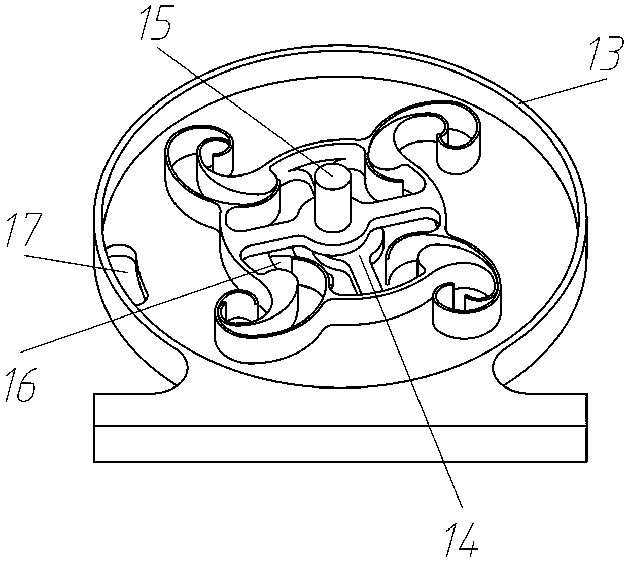
[0053] image 3 It is a schematic diagram of the internal structure of the rotary compressor of the second preferred embodiment of the present invention, such as image 3 As shown, this embodiment provides a rotor compressor based on a synchronous internal meshing double rotor structure, including a cylindrical casing 13 and a synchronous meshing double rotor. In the rotary compressor, the driven rotor is mounted on the casing through a bearing On the fixed shaft 14 on the inner and lower bottom surface, the active rotor shaft 15 is installed on the upper bottom surface of the casing through bearings and protrudes outside the casing. The cylindrical casing is in the center and the periphery of the TC unit surrounding the group separation A gas inlet 16 and a gas outlet 17 are respectively provided.

[0054] image 3 In the rotor compressor shown, rotating the driving rotor shaft 15 counterclockwise can suck gas from the inlet 16 and discharge the compressed gas from the outl...

Embodiment 3

[0056] Figure 4 It is a schematic diagram of the internal structure of the eccentric rotor compressor of the third preferred embodiment of the present invention, as Figure 4 As shown, this embodiment provides an improved eccentric rotor pump based on a synchronous meshing double rotor structure, including a cylindrical casing 18, a stator 19 and an eccentric rotor 20, and the stator 19 is equivalent to the synchronous meshing double rotor structure The TC unit of the active rotor is fixed between the two bottom surfaces in the casing, the axis of the active rotor is the axis of the stator, and the eccentric rotor 20 is equivalent to installing the passive rotor of the synchronous internal meshing double rotor on the eccentric shaft 21 through bearings, The eccentric distance of the eccentric shaft 21 is equal to the synchronous inner meshing double rotor wheelbase d, the axis of the rotation axis 22 of the eccentric rotor 20 is in line with the axis of the stator 19, and the...


PUM


Abstract

The invention provides a synchronous inner-meshing double-rotor structure as well as a rotor compressor and a rotor engine based on the synchronous inner-meshing double-rotor structure. The synchronous inner-meshing double-rotor structure is characterized in that two rotors each are provided with TC units composed of C-shaped plates and T-shaped plates, the TC units of the two rotors are the samein number, the TC units of the two rotors are arranged at intervals and are connected in a front-back mode to form a TC unit encircling group, and core plates of the T-shaped plates of each rotor arelocated in the C-shaped plates of the other rotor in front and are meshed with the C-shaped plates. In the synchronous rotation process of the two rotors, in the case of each pair of the C-shaped plate and the T-shaped plate which are meshed with each other, gas is sucked from one side of the inner side and the outer side of the TC unit encircling group, the sucked gas is compressed in closed cavities formed between the C-shaped plates and the T-shaped plates, and the compressed gas is discharged to the other side of the inner side and the outer side of the TC unit encircling group. In the case of the rotor compressor and the rotor engine based on the synchronous inner-meshing double-rotor structure have the advantages of being high in functional conversion efficiency, good in high-speed stability and high in power.

Description

technical field [0001] The invention relates to the mechanical field, in particular to a rotary compressor and a rotary engine. Background technique [0002] At present, there are mainly two types of compressors and engines widely used, piston and turbine. The piston type has a sealed closed cavity, high compression ratio, and high function conversion efficiency, but the overall structure is complex, and the reciprocating motion generates vibration. Smaller than the same volume or weight to power ratio. The turbine type has a simple structure with central symmetry, high speed and good stability. Compared with the piston type, the volume or weight-to-power ratio is larger, but the function conversion efficiency is low, and the speed range is limited. [0003] Therefore, technicians have been devoting themselves to inventing a rotary compressor and a rotary engine having the above-mentioned two types of advantages, but there are many practical application problems in existing...

Claims


Application Information

Patent Timeline
IPC IPC(8): F04C18/10F04C29/00F02B55/00F02B55/02
CPCF04C18/10F04C29/00F02B55/00F02B55/02F04C2240/30
Inventor 张满云
Owner 张满云
Why Eureka
Try Eureka