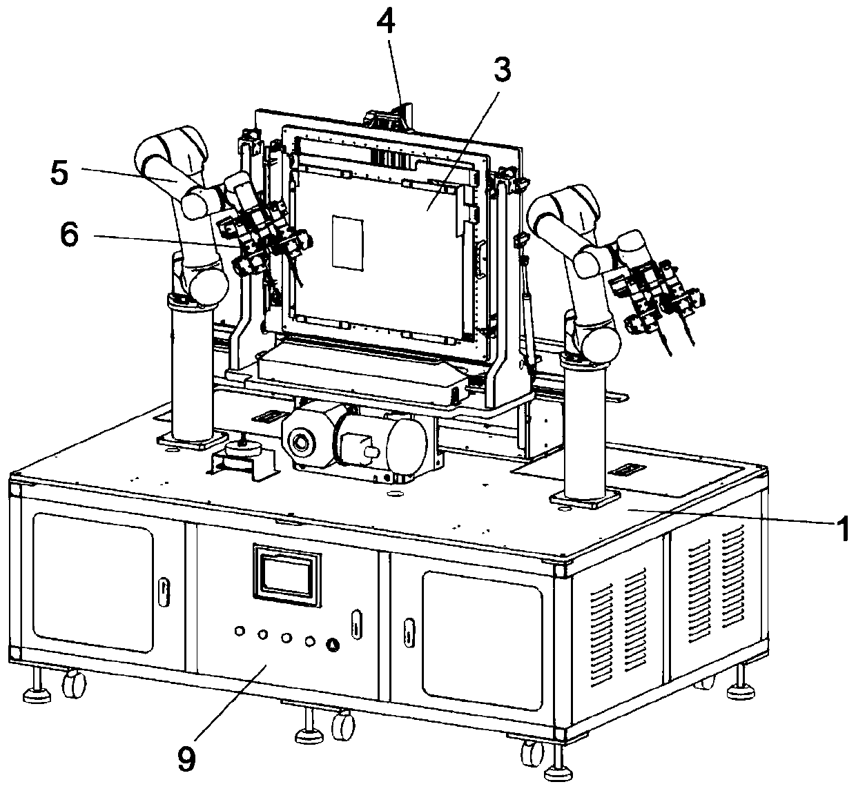
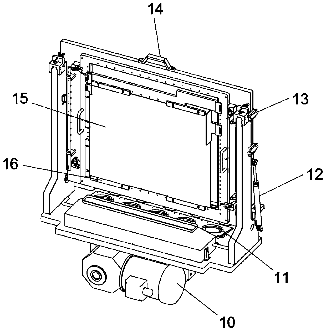
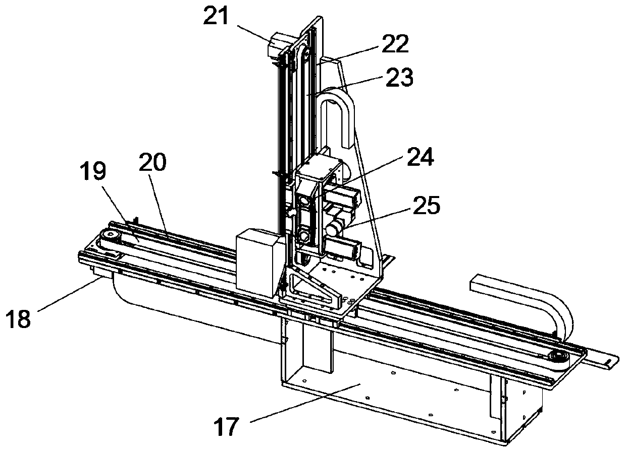
Probe automatic detection equipment and detection method thereof

An automatic detection and probe detection technology, which is applied in the direction of measuring electricity, measuring devices, and measuring electrical variables, etc., can solve the problems of difficult realization of precise flexible actions, unsatisfactory effects, and defective products, etc., to reduce product quality. The defect rate and missed detection rate are reduced, and the effect of saving time

Pending Publication Date: 2019-08-02
SHENZHEN HONG YUAN MACHINE ELECTRICAL EQUIP
View PDF0 Cites 8 Cited by
  • Summary
  • Abstract
  • Description
  • Claims
  • Application Information

AI Technical Summary

Problems solved by technology

[0002] Replacing each artificially realized processing action with equipment is the most needed innovation in this era. However, due to the limitation of the degree of freedom of the machine, many artificial actions cannot be realized in production and processing, although precise flexible actions are in processing. It will be more difficult to realize, and the achieved effect is far from the ideal state. However, the degree of freedom and processing action controlled by the machine can be realized to the greatest extent instead of manual action. Therefore, it is possible to complete the target action
[0003] In the 3C industry assembly line operation, due to the high requirements for product appearance and operation, there will be many unstable factors during manual operation, which will lead to product failure. In order to improve product yield and aesthetics, a machine is now developed to replace the manual inspection of the main board. Inspection can realize automatic 3D inspection of motherboard components, use probes to perform performance inspections on motherboard components, and automatically correct the distance position (1mm-10mm) of the probe head, which is compatible with automation equipment for products of different sizes. Therefore, we Proposed automatic probe detection equipment and its detection method

Method used


Image

  • Probe automatic detection equipment and detection method thereof
  • Probe automatic detection equipment and detection method thereof
  • Probe automatic detection equipment and detection method thereof

Examples


Embodiment Construction

[0030] The following will clearly and completely describe the technical solutions in the embodiments of the present invention with reference to the accompanying drawings in the embodiments of the present invention. Obviously, the described embodiments are only some, not all, embodiments of the present invention.

[0031] In describing the present invention, it should be understood that the terms "upper", "lower", "front", "rear", "left", "right", "top", "bottom", "inner", " The orientation or positional relationship indicated by "outside", etc. is based on the orientation or positional relationship shown in the drawings, and is only for the convenience of describing the present invention and simplifying the description, rather than indicating or implying that the referred device or element must have a specific orientation, so as to Specific orientation configurations and operations, therefore, are not to be construed as limitations on the invention.

[0032] refer to Figure ...


PUM


Abstract

The invention discloses probe automatic detection equipment, which comprises a base module. The lower end of the base module is provided with a plurality of supporting legs; and the upper end of the base module is provided with a first UR5 robot and a second UR5 robot. The first UR5 robot and the second UR5 robot are provided with a first probe detection mechanism and a second probe detection mechanism respectively. The upper end of the base module is provided with a product jig module. The upper end of the product jig module is provided with a 3D sensor motion module. One side wall of the base module is provided with an operation panel. The invention also provides a detection method of the probe automatic detection equipment. The probe automatic detection equipment is reasonable in structure design, and has the advantages of fast operation, low product defect rate, high uniformity and greatly-reduced missed inspection rate.

Description

technical field [0001] The invention relates to the technical field of automation equipment, in particular to automatic probe detection equipment and a detection method thereof. Background technique [0002] Replacing each artificially realized processing action with equipment is the most needed innovation in this era. However, due to the limitation of the degree of freedom of the machine, many artificial actions cannot be realized in production and processing, although precise flexible actions are in processing. It will be more difficult to realize, and the achieved effect is far from the ideal state. However, the degree of freedom and processing action controlled by the machine can maximize the realization of replacing manual action. Therefore, it is possible to complete the target action. [0003] In the 3C industry assembly line operation, due to the high requirements for product appearance and operation, there will be many unstable factors during manual operation, which...

Claims


Application Information

Patent Timeline
Patent Type & Authority Applications(China)
IPC IPC(8): G01R31/00G01R1/04G01R1/073G01B11/24G01B11/00G01B5/00
CPCG01B5/0002G01B11/00G01B11/24G01R1/04G01R1/07392G01R31/00
Inventor 吴天荣
Owner SHENZHEN HONG YUAN MACHINE ELECTRICAL EQUIP
Why Eureka
Try Eureka