Novel drive motor for electric vehicle
A technology for electric vehicles and driving motors, which is applied in the direction of electric vehicles, motors, electric components, etc., can solve the problems of motor damage, poor heat dissipation, high energy consumption, etc., to improve cooling and shock absorption efficiency, increase heat dissipation, The effect of accelerating heat exchange
- Summary
- Abstract
- Description
- Claims
- Application Information
AI Technical Summary
Problems solved by technology
Method used
Image
Examples
Embodiment 1
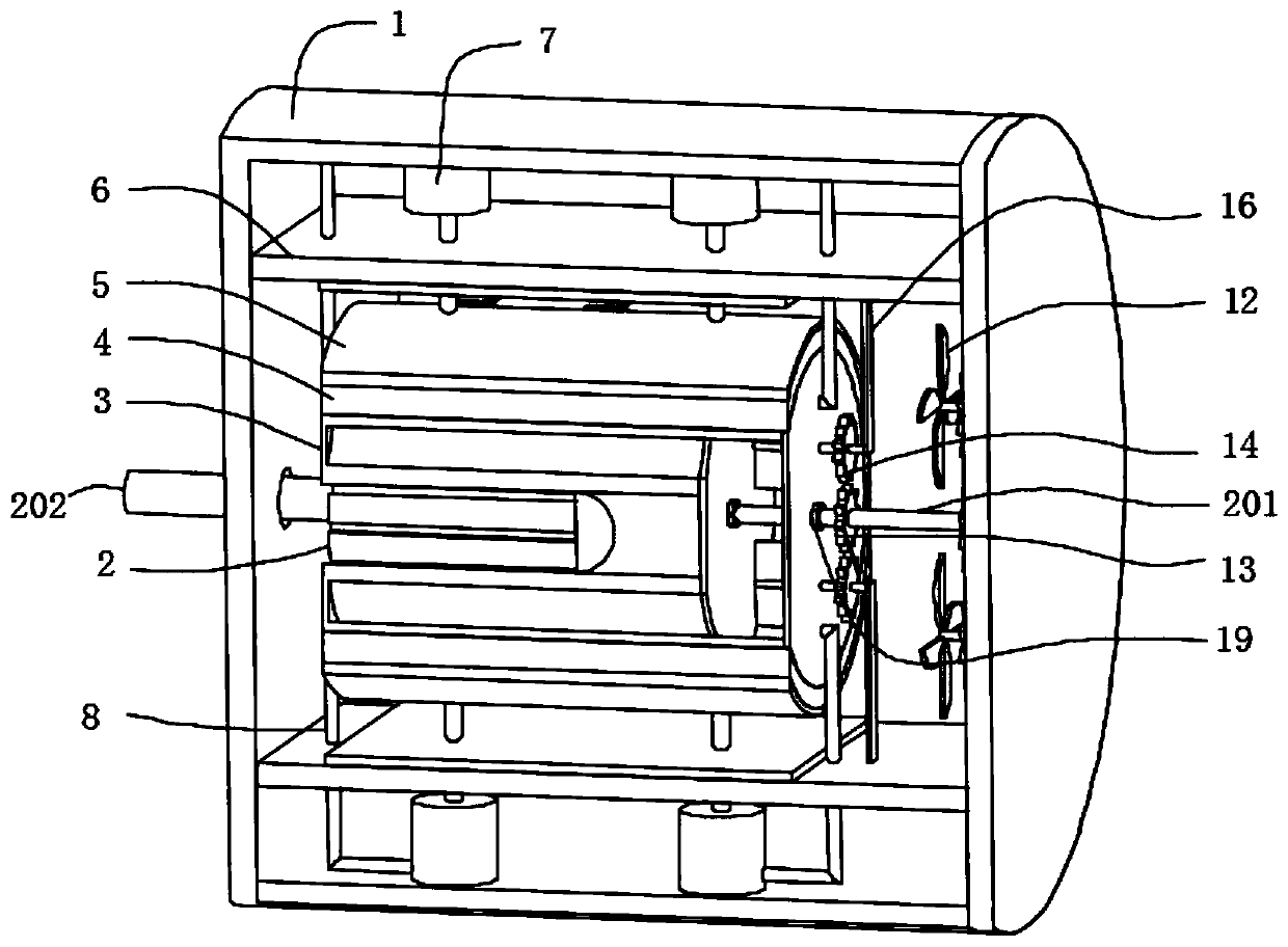
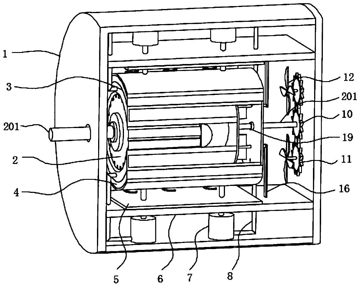
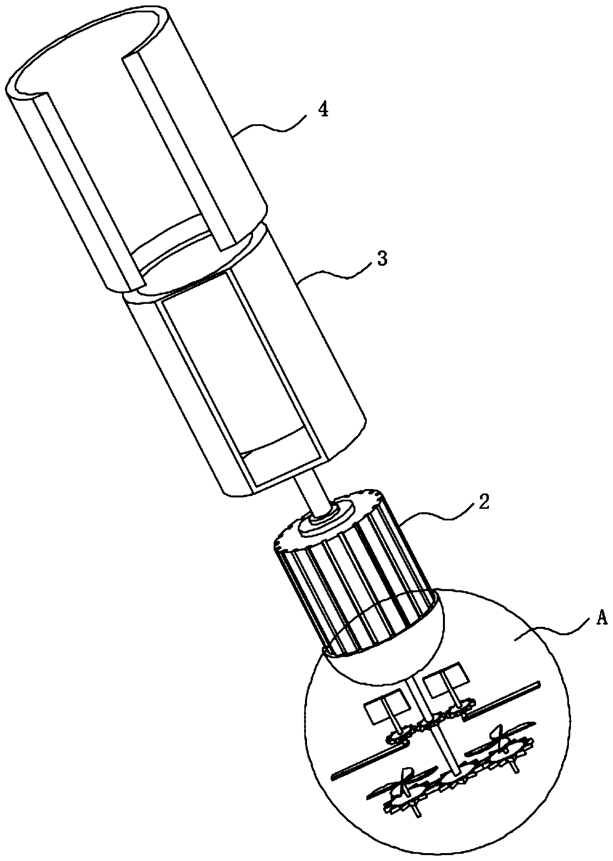
[0034] refer to Figure 1-3 , a new drive motor for electric vehicles, including a protective shell 1 and a motor body 2, the inner side wall of the protective shell 1 is connected with a symmetrically distributed baffle 6, the opposite side of the baffle 6 is connected with a shock-absorbing splint 5, and the protective shell 1 The inner side wall is connected with a piston cylinder 7, the top of the piston cylinder 7 is slidably connected with a piston rod 9, the end of the piston rod 9 away from the piston cylinder 7 is connected with the damping splint 5 through the baffle plate 6, and the piston cylinder 7 is connected on the side wall near the bottom end. There is a water pipe 8, a heat exchange jacket 3 is connected to the outer wall of the motor body 2, the motor body 2 is connected with the damping splint 5 through the heat exchange jacket 3, and the end of the water pipe 8 away from the piston cylinder 7 is communicated with the inner cavity of the heat exchange jacke...
Embodiment 2
[0036] refer to Figure 4, a new driving motor for electric vehicles, which is basically the same as Embodiment 1, the difference is that the stirring assembly includes stirring blades 15, and the stirring blades 15 are connected with the outer wall of the first drive shaft 201 placed inside the heat exchange jacket 3, and the first A drive shaft 201 is placed on the inner outer wall of the protective shell 1 and is connected to the first driving gear 13. The top end of the baffle plate 6 is connected to a support plate 16. The support plate 16 is rotatably connected to a first rotating shaft 17, and the first rotating shaft 17 is away from the support plate. One end of 16 is connected with the first driven gear 14, the first driven gear 14 is meshed with the first driving gear 13, the rotation of the first drive shaft 201 drives the first driving gear 13 connected to it to rotate, and the first driving gear 13 drives The first driven gear 14 meshing with it rotates, and the f...
Embodiment 3
[0038] refer to Figure 5 , a new type of drive motor for electric vehicles, basically the same as Embodiment 2, the difference is that the shock-absorbing pad 4 is connected to the top of the shock-absorbing splint 5, and the shock-absorbing pad 4 is connected to the inner wall of the bottom of the shock-absorbing splint 5. The first spring 501 .
[0039] The first spring 501 is a butterfly spring.
[0040] When the motor body 2 squeezes the shock-absorbing plate 5, the shock-absorbing washer 4 connected to the shock-absorbing plate 5 will sag and squeeze the first spring 501 connected to it. plate 4, so as to give the motor body 2 a buffer force to make it shake slightly, and the butterfly spring makes the buffer of the motor body 2 more stable.
PUM
 Abstract
Description
Claims
Application Information
 - R&D
- Intellectual Property
- Life Sciences
- Materials
- Tech Scout
- Unparalleled Data Quality
- Higher Quality Content
- 60% Fewer Hallucinations
Browse by: Latest US Patents, China's latest patents, Technical Efficacy Thesaurus, Application Domain, Technology Topic, Popular Technical Reports.
© 2025 PatSnap. All rights reserved.Legal|Privacy policy|Modern Slavery Act Transparency Statement|Sitemap|About US| Contact US: help@patsnap.com


