
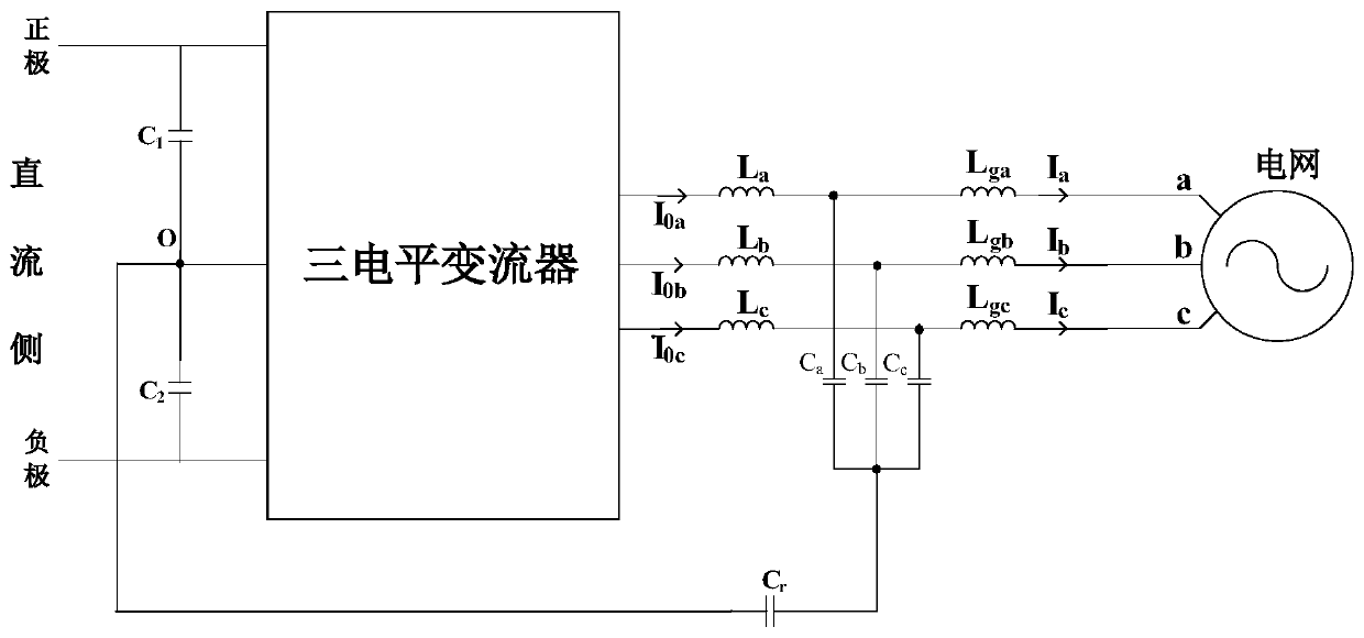
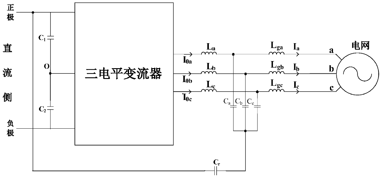
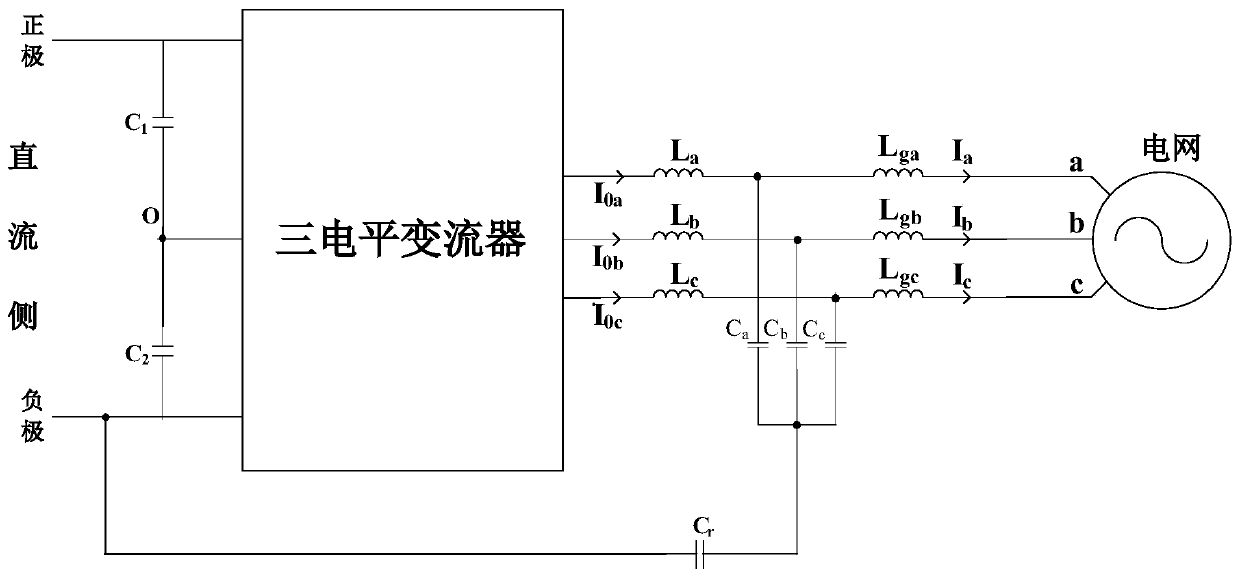
A mid-point self-balancing three-level grid-connected converter topology

A three-level, converter technology, which is applied in the direction of converting AC power input to DC power output, electrical components, single-network parallel feeding arrangement, etc., can solve the problem of increasing harmonic distortion and long transient recovery time of midpoint potential , Without considering the deviation of the capacitance value of the DC side, etc., the effect of avoiding unequal voltage stress, increasing the voltage equalization time, and improving the service life

Active Publication Date: 2020-07-28
BEIJING JIAOTONG UNIV +1
View PDF5 Cites 0 Cited by
  • Summary
  • Abstract
  • Description
  • Claims
  • Application Information

AI Technical Summary

Problems solved by technology

When the circuit uses the SVPWM modulation method, the midpoint potential is adjusted by changing the action time of the redundant vector by measuring the capacitance potential difference, but this method suffers from increased harmonic distortion, complex control strategies and more voltage sensors. Cost; by introducing the coefficient of the relationship between the midpoint current and the midpoint potential of the capacitor, the value of the injected midline current is calculated according to the midpoint voltage difference, but this method does not take into account the deviation of the DC side capacitance value. This algorithm is not well applicable; the concept of self-balancing can naturally stabilize the neutral point at the midpoint of the DC side. Due to the self-adjustment of the traditional circuit, the transient time for the midpoint potential to recover is relatively long. In order to make the circuit quickly reach equilibrium , by connecting the RLC regulator circuit in parallel with the load, the circuit transient recovery time can be shortened
However, this circuit is mainly used for the converter connected to the load, the load affects each other on the self-balancing effect, and the RLC branch increases the loss of the circuit, and the mid-point self-balancing mechanism of the grid-connected converter is not clear

Method used


Image

  • A mid-point self-balancing three-level grid-connected converter topology
  • A mid-point self-balancing three-level grid-connected converter topology
  • A mid-point self-balancing three-level grid-connected converter topology

Examples


Embodiment Construction

[0038] In order to make the object, technical solution and advantages of the present invention clearer, the present invention will be further described in detail below in conjunction with the accompanying drawings and embodiments. It should be understood that the specific embodiments described here are only used to explain the present invention, not to limit the present invention.

[0039] On the contrary, the invention covers any alternatives, modifications, equivalent methods and schemes within the spirit and scope of the invention as defined by the claims. Further, in order to make the public have a better understanding of the present invention, some specific details are described in detail in the detailed description of the present invention below. The present invention can be fully understood by those skilled in the art without the description of these detailed parts.

[0040] In the prior art, the three-level converter has the technical problem of midpoint potential dri...


PUM


Abstract

The invention belongs to the technical field of power electronics and is used for a distributed generation system, and particularly relates to a three-level grid-connected converter midpoint self-balancing topology comprises a three-level converter, inductors La, Lb, Lc, Lga, Lgb and Lgc, a capacitor Ca, a capacitor Cb, a capacitor Cc, a capacitor Cr and a capacitor C1 and a capacitor C2 which arearranged on the DC side. According to the topology, fast and equal voltage distribution of the DC side can be realized when the voltage distribution of the DC side capacitors C1 and C2 is uneven, andthe equal voltage distribution of the DC side can be maintained. The topology can realize self-balancing of the DC side midpoint potential without increasing the switching device and the DC side voltage sensor so that the unequal voltage stress of the switching tube can be avoided and the grid-connected current quality and the service life of the converter can be enhanced.

Description

technical field [0001] The invention belongs to the technical field of power electronics, and in particular relates to a midpoint self-balancing three-level grid-connected converter topology, which is used in a distributed power grid-connected system. Background technique [0002] With the rapid development of distributed power, grid-connected converters have played a pivotal role as the interactive interface between distributed power and the grid. Three-level neutral-point clamped NPC and T-NPC structure converters are widely used in high-power systems due to their low output harmonic content. Ideally, the DC side of the three-level converter is composed of two voltage-dividing capacitors with the same parameters in series, and the voltage of the capacitor is half of the DC bus voltage. There are factors such as even harmonics and unbalanced operation of three-phase loads, and there is a problem of midpoint potential drift. The midpoint potential drift will deteriorate th...

Claims


Application Information

Patent Timeline
Patent Type & Authority Patents(China)
IPC IPC(8): H02M7/487H02J3/38
CPCH02J3/38H02M7/487
Inventor 唐芬陈鹏飞刘京斗吴学智王玮
Owner BEIJING JIAOTONG UNIV
Learn More