Combined gasification burner and use method thereof

A combined type, gasification chamber technology, applied in the direction of granular/powdered fuel gasification, etc., can solve the problem of affecting the performance of the main burner, increasing the difficulty of processing the furnace cover of the gasifier, the difficulty of installing the main burner, the auxiliary burner, the main Burner flow field interference and other problems, to achieve the effect of accelerating the gasification reaction rate, improving fuel conversion rate and increasing the contact area

Pending Publication Date: 2019-08-06
BEIJING AEROSPACE MWAY TECH CO LTD
View PDF1 Cites 1 Cited by
  • Summary
  • Abstract
  • Description
  • Claims
  • Application Information

AI Technical Summary

Problems solved by technology

However, this arrangement not only increases the processing difficulty of the gasifier cover and the installation difficulty of the main burner and auxiliary burner, but also the high-speed airflow ejected from the auxiliary burner will interfere with the flow field of the main burner. Affect the performance of the main burner

Method used


Image

  • Combined gasification burner and use method thereof
  • Combined gasification burner and use method thereof
  • Combined gasification burner and use method thereof

Examples


Embodiment 1

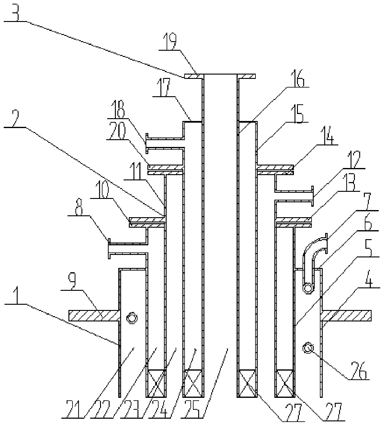
[0058] figure 1 A schematic cross-sectional view of an embodiment of the combined gasification burner provided by the present invention, as figure 1 Shown:

[0059] The combined gasification burner of this embodiment includes: a first part 1, a second part 2 and a third part 3 which are coaxially fitted sequentially from outside to inside. Each part is independent of each other and connected as a whole by fasteners. The inner diameter of the first part 1 is larger than the outer diameter of the second part 2 , and the inner diameter of the second part 2 is larger than the outer diameter of the third part 3 . The first part 1 and the third part 3 respectively have independent fuel passages and oxidant passages.

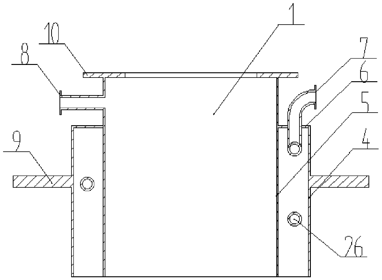
[0060] figure 2 for figure 1 A schematic cross-sectional view of the first part of the illustrated embodiment, such as figure 2 Shown:

[0061] The first component 1 includes a first component outer tube 4 and a first component inner tube 5 arranged coaxially i...


PUM


Abstract

The invention relates to a combined gasification burner and a use method thereof. The burner comprises a first component, a second component and a third component, wherein the first component, the second component and the third component are coaxially and sequentially sleeved from outside to inside, the first component, the second component and the third component are independent of each other, and are integrally connected by fasteners, and the first component and the third component respectively have a separate fuel channel and an oxidant channel. Compared with the gasification burner only having the single-path fuel and the single-path oxidant, the combined gasification burner of the embodiments of the present invention increases the numbers of the fuel channels and the oxidant channels,increases the contact area between the fuel and the oxidant, ensures the rapid, complete and uniform doping of the fuel and the oxidant, and improves the fuel conversion rate and the burner performance in the case of the same total feeding amount, the same gasification chamber reaction space and the same residence time.

Description

technical field [0001] The invention relates to the technical field of high-temperature and high-pressure gasification reaction equipment for coal, in particular to a gasification burner. Background technique [0002] In the field of high-temperature and high-pressure coal gasification, there are common problems such as slow gasification reaction speed and low fuel conversion rate in the process of industrial application of coal gasification equipment. The gasification burner is one of the core equipment of the coal gasification plant, and its performance directly determines the safety, stability and economy of the coal gasification plant. In the small reaction space and short residence time of the gasification chamber, mixing the fuel and oxidant as fully and evenly as possible is the key factor to speed up the gasification reaction rate, improve the fuel conversion rate and the performance of the gasification burner. [0003] In the existing coal gasification technology, ...

Claims


Application Information

Patent Timeline
Patent Type & Authority Applications(China)
IPC IPC(8): C10J3/50
CPCC10J3/50
Inventor 魏佳张礼李锡华
Owner BEIJING AEROSPACE MWAY TECH CO LTD
Why Eureka
Try Eureka