High-efficiency positive-pressure gas turbine

A gas turbine, high-efficiency technology, applied in the direction of gas turbine devices, combustion air/combustion-air treatment, mechanical equipment, etc., can solve the aerodynamic noise and mechanical noise generated by the main body of the gas turbine, affect the normal work of the staff, and the main body of the gas turbine is easily damaged, etc. problems, to achieve the effect of heat insulation, reduce assembly workload, and improve work comfort

Inactive Publication Date: 2019-08-06
JIANGSU MARITIME INST
View PDF1 Cites 2 Cited by
  • Summary
  • Abstract
  • Description
  • Claims
  • Application Information

AI Technical Summary

Problems solved by technology

[0003] The invention patent "Positive Pressure Gas Turbine" (application number: CN201710200915.0) has the following problems: First, the main body of the gas turbine is arranged in a "bare metal" state, which lacks protective functions, and the installation and fixing are not stable enough, and the reliability is low. The second is that the gas turbine will generate vibration when it is work

Method used


Image

  • High-efficiency positive-pressure gas turbine
  • High-efficiency positive-pressure gas turbine
  • High-efficiency positive-pressure gas turbine

Examples


Example Embodiment

[0026] Example one

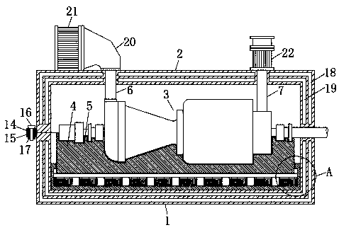
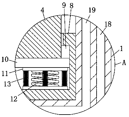
[0027] Reference Figure 1-4 , A high-efficiency positive pressure gas turbine, comprising a gas turbine main body 3 arranged in a lower box body 1 and an upper box body 2, the lower end of the gas turbine body 3 is provided with a mounting seat 4, and the upper end side wall of the mounting seat 4 is provided with The installation groove 5 matched with the lower end side wall of the gas turbine main body 3, during use and installation, first place the gas turbine main body 3 in the lower box body 1, and the gas turbine main body 3 can be placed in the installation groove 5 on the installation seat 4 for installation The groove 5 is matched with the lower end side wall of the gas turbine main body 3. The gas turbine main body 3 has a certain dead weight. The lower end side wall of the gas turbine main body 3 can abut the inner wall of the installation groove 5, and the gas turbine main body 3 can be firmly placed on the installation groove 5. Therefore, the ...

Example Embodiment

[0037] Example two

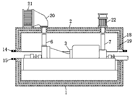
[0038] Reference Figure 5 The difference between this embodiment and the first embodiment is that an air filter 23 is connected to the end of the intake muffler 21 away from the intake housing 20, and the air filter 23 communicates with the intake muffler 21. The working principle of the cleaner 23 and the connection method with the intake muffler 21 are in the prior art, and will not be described here. The air cleaner 23 can provide clean air for the gas turbine main body 3 to prevent the gas turbine main body 3 from working Inhaling air with impurity particles increases the probability of abrasion and damage, thereby improving work efficiency.


PUM


Abstract

The invention discloses a high-efficiency positive-pressure gas turbine. The high-efficiency positive-pressure gas turbine comprises a gas turbine body which is arranged in a lower case body and an upper case body. A mounting base is arranged at the lower end of the gas turbine body. According to the high-efficiency positive-pressure gas turbine, the gas turbine body is mounted in a mounting groove in the mounting base, so that mounting and fixing are convenient and firm; and the gas turbine body is arranged in the upper case body and the lower case body, so that the gas turbine body is well protected, and the working reliability is improved; a damping base is arranged so that the gas turbine body can be well damped and supported; a gas inlet silencing mechanism and a gas outlet silencingmechanism are arranged, and a first sound insulation layer and a second sound insulation layer are arranged in the upper case body and the lower case body, so that pneumatic noise and mechanical noisegenerated when the gas turbine body works are effectively lowered; and overall structure is beneficial to heat insulation, sound insulation and shock prevention, so that the working environment is improved, the working comfort of workers is improved, and the working efficiency is improved.

Description

Technical field [0001] The invention relates to the technical field of positive pressure gas turbines, in particular to a high-efficiency positive pressure gas turbine. Background technique [0002] Positive pressure gas turbines are widely used in industries, shipbuilding, power plants and other industries. Gas turbines use continuous gas as a working medium to drive the impeller to rotate at a high speed and convert the energy of the fuel into useful work. A rotating impeller heat engine. [0003] The invention patent "Positive Pressure Gas Turbine" (application number: CN201710200915.0) has the following problems: First, the main body of the gas turbine is arranged in a "bare metal" state, which lacks protective functions, is not stable enough to install and fix, and has low reliability. The main body of the gas turbine is vulnerable The second is that the gas turbine will produce vibration when it is working, and it lacks shock absorption; the third is that the main body of th...

Claims


Application Information

Patent Timeline
IPC IPC(8): F02C7/04F02C7/045
CPCF02C7/04F02C7/045
Inventor 王松明
Owner JIANGSU MARITIME INST
Why Eureka
Try Eureka