Dehumidifier

A dehumidifier and casing technology, applied in the field of dehumidification equipment, can solve the problems of large volume, complex structure, and high cost of dehumidifiers, and achieve the effects of reduced volume and weight, reasonable air duct layout, and good dehumidification effect

Pending Publication Date: 2019-08-06
BEIJING SMARTMI TECH
View PDF0 Cites 1 Cited by
  • Summary
  • Abstract
  • Description
  • Claims
  • Application Information

AI Technical Summary

Problems solved by technology

[0003] However, in the existing dehumidifiers that use compressor refrigeration, the humid air is first blown onto the evaporator for condensation, and the initial temperature (room temperature) of the humid air remains unchanged from the initial temperature (set temperature) of the evaporator. That is, the temperature difference between the two remains unchanged, the dew point temperature of the humid air remains unchanged, and the condensation efficiency cannot be improved; in addition, the condenser in the dehumidifier will release heat, and this part of the heat will enter the room, resulting in an increase in the indoor temperature; and the inside of the dehumidifier There are many parts used, and its structure is more complicated, resulting in a larger volume and higher cost of the dehumidifier

Method used


Image

  • Dehumidifier
  • Dehumidifier
  • Dehumidifier

Examples


Embodiment Construction

[0019] The technical solutions in the embodiments of the present invention will be clearly and completely described below in conjunction with the accompanying drawings in the embodiments of the present invention. Obviously, the described embodiments are only some, not all, embodiments of the present invention. Based on the embodiments of the present invention, all other embodiments obtained by persons of ordinary skill in the art without making creative efforts belong to the protection scope of the present invention.

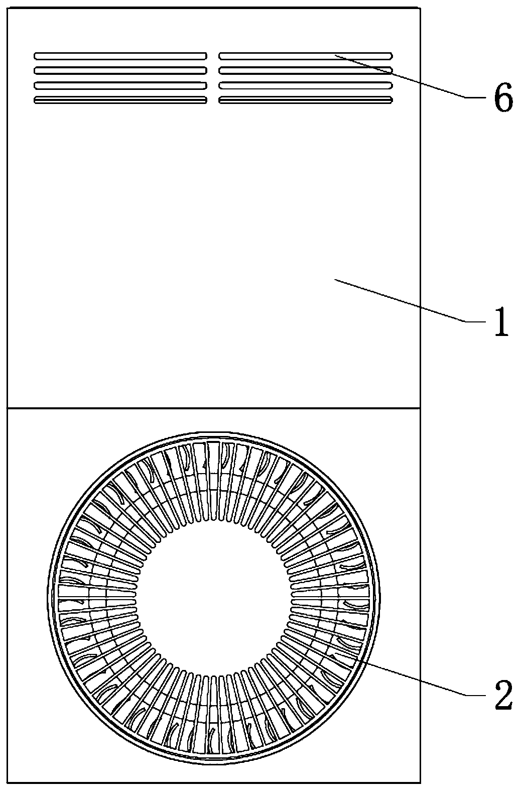
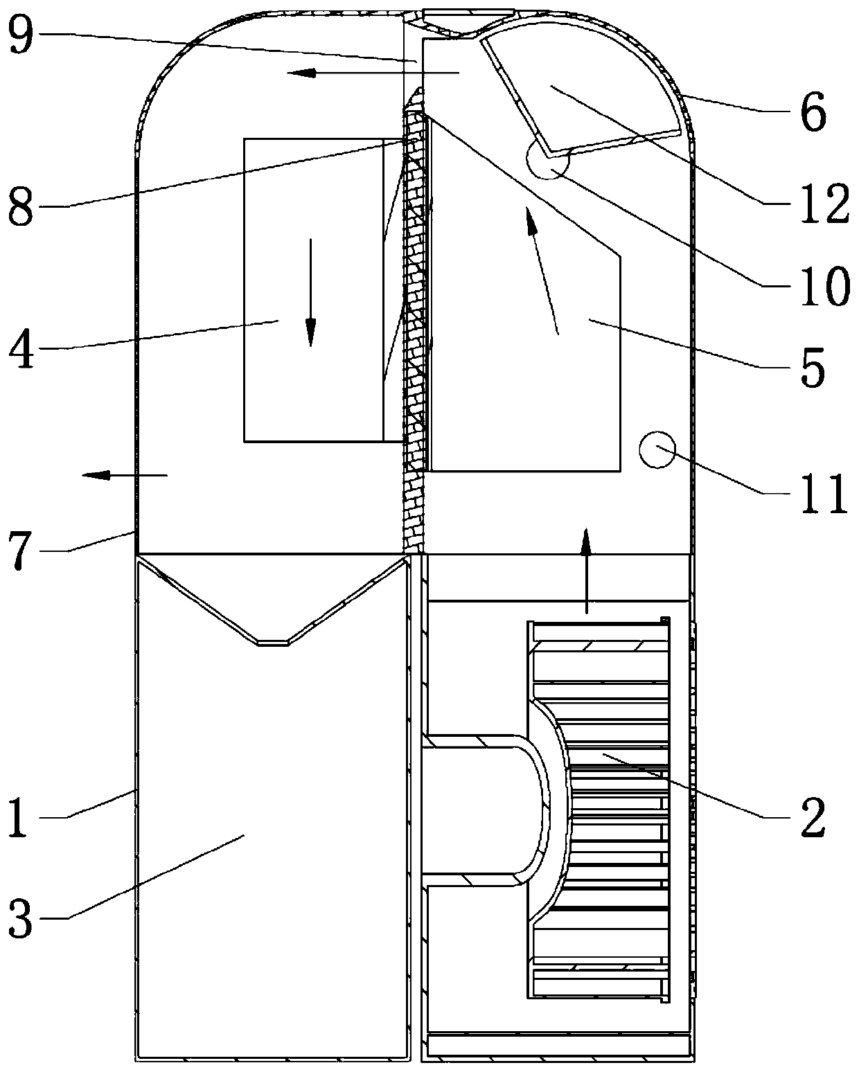
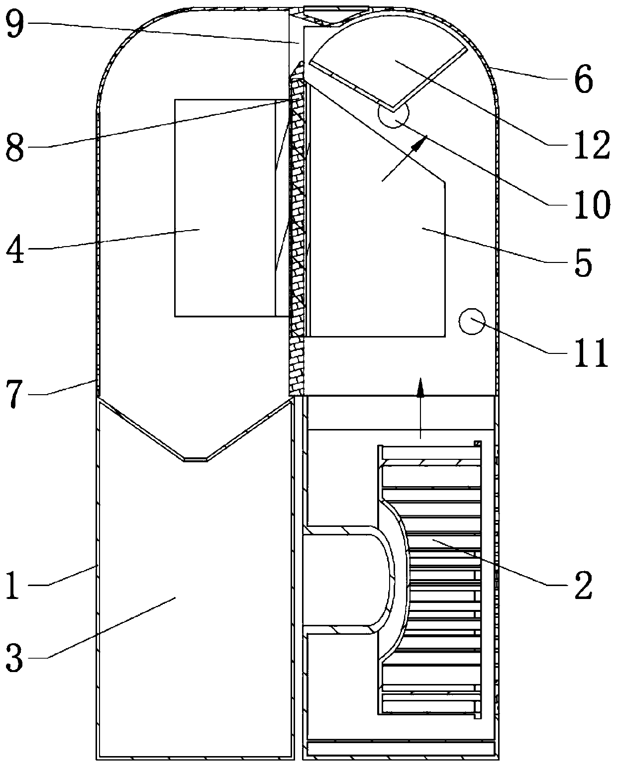
[0020] Such as Figure 1 to Figure 3 The specific embodiment shown is a dehumidifier, including a casing 1, a centrifugal bellows 2 and a water storage tank 3. A partition 8 is arranged inside the casing 1, and the partition 8 separates the inside of the casing 1. In order to heat the chamber and the condensing chamber, the partition plate 8 is provided with a semiconducting cooling sheet, and the semiconducting cooling sheet includes heat dissipation fins 5 and...


PUM


Abstract

The invention provides a dehumidifier comprising a machine shell, a centrifugal air bellow and a water storage tank. The machine shell is internally provided with a heating chamber and a condensationchamber, the heating chamber is internally provided with heat dissipating fins, and the condensation chamber is internally provided with condensation fins; the water storage tank is located below thecondensation chamber and communicates with the bottom of the condensation chamber, the centrifugal air bellow is located below the heating chamber, an air outlet is in communication with the bottom ofthe heating chamber, the machine shell is provided with a hot air outlet communicating with the heating chamber and a cold air outlet communicating with the condensation chamber, an internal air opening is formed between the upper end of a partition and the machine shell, and opening degree adjustment devices are arranged on the hot air outlet and the internal air opening; a dehumidification channel is formed from the centrifugal air bellow to the heating chamber to the internal air opening to the condensation chamber to the cold air outlet; and a hot air channel is formed from the centrifugal air bellow to the heating chamber to the hot air outlet, and the opening degree adjusting devices control the air volume of the dehumidification channel and the hot air channel. A semiconductor refrigerating chip replaces a compressor, the condensation efficiency is improved, the size and weight of the whole machine are reduced, and the cost is reduced.

Description

technical field [0001] The invention relates to the technical field of dehumidification equipment, in particular to a dehumidifier. Background technique [0002] The dehumidification principle of the dehumidifier is: the indoor humid air is sucked into the dehumidifier, the moisture in the air is condensed into water droplets inside the dehumidifier and stored in the water tank, and finally the dehumidified air is discharged out of the dehumidifier to achieve the purpose of indoor dehumidification. In the prior art, most dehumidifiers are composed of a compressor, a condenser, an evaporator, a fan, a water storage tank, a casing and a controller. In principle, the compressor is used for refrigeration. After the humid air passes through the evaporator, the evaporator absorbs heat, the air temperature decreases, and the water vapor in the humid air condenses into water droplets to achieve the purpose of dehumidification. [0003] However, in the existing dehumidifiers that us...

Claims


Application Information

Patent Timeline
Patent Type & Authority Applications(China)
IPC IPC(8): F24F3/14F24F11/89F25B21/02F28F3/02
CPCF24F3/14F24F11/89F25B21/02F28F3/02
Inventor 郝玉龙
Owner BEIJING SMARTMI TECH
Why Eureka
Try Eureka