
Test method for electrical system circuits formed by busbars connected through tie switches

A technology for tie switches and electrical systems, which is applied in the field of testing electrical system loops, can solve problems such as incorrect bus phase connection on both sides of the tie switch, short circuit of the tie switch, troublesome operation, etc. safety effect

Active Publication Date: 2021-10-01
SHANGHAI ERSHIYE CONSTR CO LTD +1
View PDF5 Cites 0 Cited by
  • Summary
  • Abstract
  • Description
  • Claims
  • Application Information

AI Technical Summary

Problems solved by technology

This method has the following disadvantages: (1) two power supplies are required, and the operation is troublesome; (2) for two busbars installed in the same column, it is not easy to find that the two busbars are directly connected and the tie switch is short-circuited during the installation process of the tie switch Wrong installation problem; (3) For the two rows of busbars installed opposite to each other on the panel, it is not easy to find the wrong connection of the busbar phases on both sides of the tie switch, and it may cause the phase-to-phase short circuit of the tie switch at the moment of closing

Method used


Image

  • Test method for electrical system circuits formed by busbars connected through tie switches
  • Test method for electrical system circuits formed by busbars connected through tie switches
  • Test method for electrical system circuits formed by busbars connected through tie switches

Examples


Embodiment Construction

[0029] The present invention is further illustrated below by specific examples.

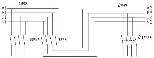
[0030] A method for testing an electrical system loop formed by busbars connected by a tie switch, comprising step 1, dividing the electrical system into a busbar section, busbar sections 2, busbar inter-busbar tie switches, and power supply for busbar section 1 according to the schematic diagram of the electrical system No. 1 incoming line, No. 2 incoming line supplying power to the 2-section busbar, and the respective feed-out circuits of the two busbar sections;

[0031] Step 2. Check the two sections of busbar, incoming line switch, tie switch and all outgoing switches;

[0032] Step 3, change the tie switch to hot standby state;

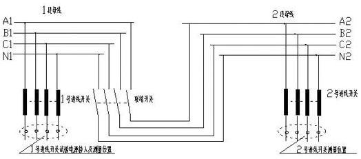
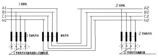
[0033] Step 4. Introduce a three-phase low-voltage power supply to No. 1 incoming line;

[0034] Step 5. Change the No. 1 incoming line switch and No. 2 incoming line switch to the running state;

[0035] Step 6. Measure and record the voltage on the receiving s...


PUM


Abstract

The invention specifically relates to an electrical circuit testing method composed of two sections of busbars connected by a tie switch. Including being familiar with the electrical system and its schematic diagram; checking the two-section busbar, incoming line switch, tie switch and all outgoing switches; changing the tie switch to hot standby state; introducing a three-phase low-voltage power supply to No. 1 incoming line; Change the incoming line switch and the No. 2 incoming line switch to the running state; respectively measure and record the voltage on the power receiving side of the two incoming line switches, and make judgments; change the contact switch to the running state; on the receiving side of the two incoming line switches Measure and record the voltage respectively, and make a judgment; measure the voltage at the receiving side of the incoming line switch of the two busbars. The invention only needs one low-voltage test power supply; it is suitable for a wide range, from low voltage to high voltage, and is applicable to three-phase three-wire systems and three-phase four-wire systems; it can quickly find out the direct connection error and connection of two busbars at the connection switch during installation. The bus phase connection on both sides of the switch is wrong, which greatly improves the safety of the system.

Description

technical field [0001] The invention relates to the field of electrical system loop detection, in particular to a testing method for an electrical system loop formed by a bus bar connected by a tie switch. Background technique [0002] In the high and low voltage power supply and distribution systems, in order to ensure the normal operation of the important loads on each bus section and improve the reliability of power supply, the primary or secondary busbars of the system are often connected through contact switches. The premise of the safe operation of the tie switch between the two sections of busbars is that the phases of the two sections of busbars are consistent and the circuit connection is correct. The routine inspection method is: use two separate power sources whose phase relationship has been confirmed to supply power to their respective busbars, and measure the phase of the two power sources at the break of the tie switch to ensure the correctness of the circuit ...

Claims


Application Information

Patent Timeline
IPC IPC(8): G01R31/00
CPCG01R31/00
Inventor 李贵平郑守华倪振刚
Owner SHANGHAI ERSHIYE CONSTR CO LTD
Features
  • Generate Ideas
  • Intellectual Property
  • Life Sciences
  • Materials
  • Tech Scout
  • Unparalleled Data Quality
  • Higher Quality Content
  • 60% Fewer Hallucinations
Learn More