Switching state detecting circuit, over phase splitting device, detecting method and control method

A state detection and detection circuit technology, which is used in measuring devices, circuit breaker testing, and current-only measurement, etc., can solve problems such as short-circuit current generation, and achieve the effects of improving efficiency, high detection efficiency, and improving stability and reliability.

Active Publication Date: 2019-08-06
ZHUZHOU CSR TIMES ELECTRIC CO LTD
View PDF15 Cites 3 Cited by
  • Summary
  • Abstract
  • Description
  • Claims
  • Application Information

AI Technical Summary

Problems solved by technology

For example, electronic switches such as thyristors have a time delay when they are completely turned off. In the above-mentioned over-phase separation process, when controlling the switching of two commutation switches, usually after the previous switch is turned off, the latter one is turned on after a certain period of time delay. Switch, as mentioned above, when the switch SCR_V1 is turned off, then delay to turn off SCR_V2, but if the previous switch has not been completely turned off, turning on another switch at this time will cause a short-circuit current

Method used


Image

  • Switching state detecting circuit, over phase splitting device, detecting method and control method
  • Switching state detecting circuit, over phase splitting device, detecting method and control method
  • Switching state detecting circuit, over phase splitting device, detecting method and control method

Examples


Embodiment 1

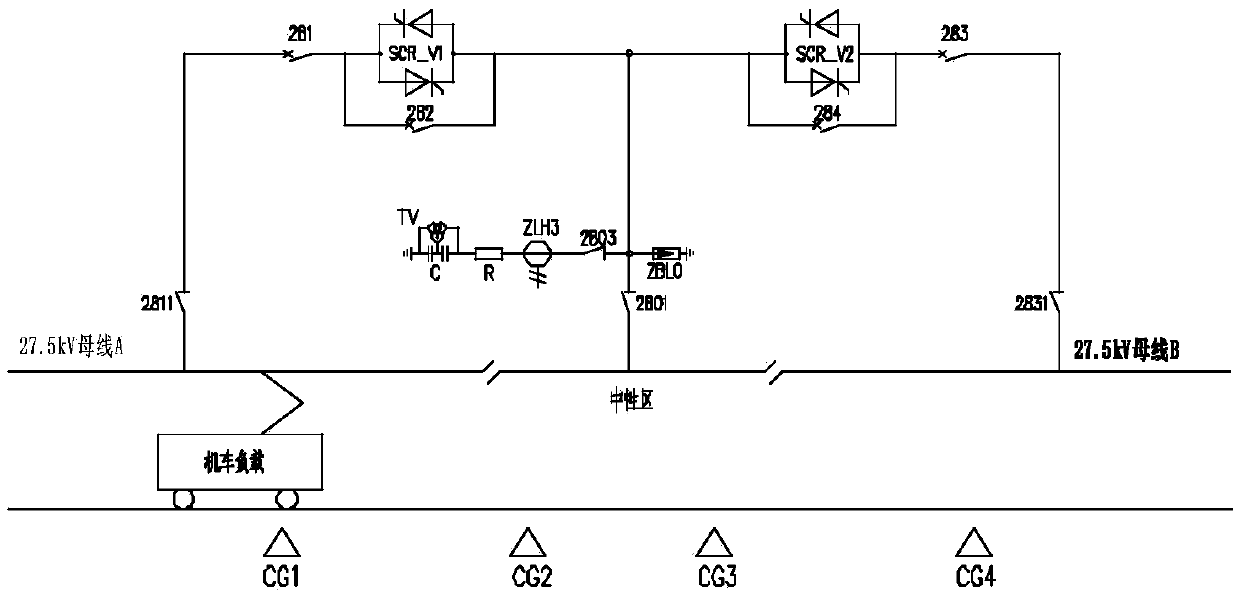
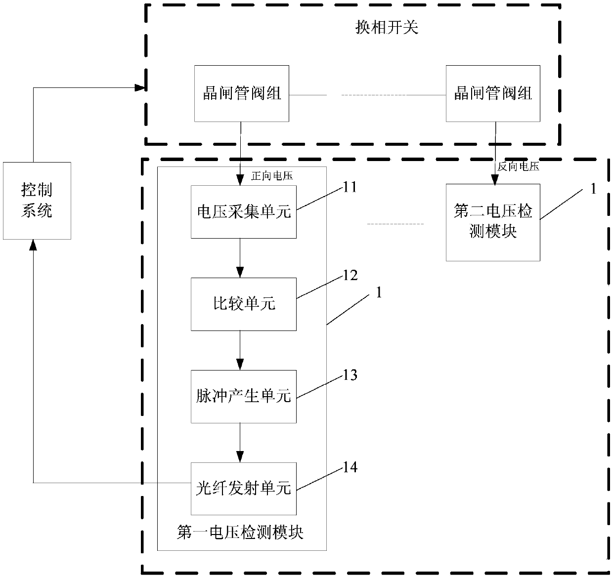
[0040] like figure 2 As shown, this embodiment is used for the state detection circuit of the commutation switch for over-phase control. The commutation switch includes more than two thyristor valve groups connected in sequence, and each thyristor valve group includes two thyristors connected in anti-parallel connection. The detection circuit includes More than two voltage detection modules 1, each voltage detection module 1 is correspondingly connected to both ends of a thyristor valve group, and is used to detect the voltage state of the corresponding thyristor valve group, wherein at least one voltage detection module 1 is configured to detect the corresponding The forward voltage state of the thyristor valve group, at least one voltage detection module 1 is configured to detect the reverse voltage state of the corresponding thyristor valve group.

[0041] When the reversing switch is composed of two or more thyristor valve groups connected, if the reversing switch is turn...

Embodiment 2

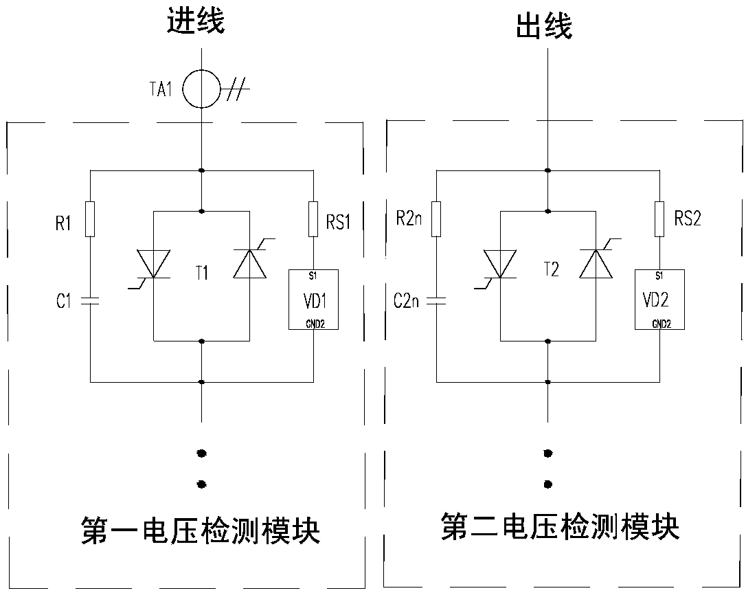
[0063] This embodiment is basically the same as Embodiment 1, except that each commutation switch in this embodiment specifically includes 2N (N is an integer, and N>1) thyristor valve groups connected in series in sequence, and the detection circuit includes 2N voltage Detection module 1, that is, each thyristor valve group is correspondingly equipped with a voltage detection module 1, such as Figure 7 As shown, each voltage detection module 1 is correspondingly connected to a thyristor valve group, wherein the voltage detection module 1 (T1~Tn) corresponding to the first N thyristor valve groups is configured as the first voltage detection module, and the last N thyristor valve groups correspond to The voltage detection module 1 (Tn+1~T2n) is configured as the second voltage detection module. The direction of the incoming and outgoing lines of the T1~Tn thyristors and the Tn+1~T2n thyristor stages is opposite. , the voltage detection module VD1~VDn corresponding to T1~Tn fe...


PUM


Abstract

The invention discloses a switching state detecting circuit, an over phase splitting device, a detecting method and a control method. The detecting circuit comprises more than two voltage detecting modules; each voltage detecting module is correspondingly connected to two ends of a thyristor valve group and is used for detecting the voltage state of the thyristor valve group. At least one voltagedetecting module is configured to detect a forward voltage state of the thyristor valve group; and at least one voltage detecting module is configured to detect a reverse voltage state of the thyristor valve group. According to the over phase splitting device, each commutation switch is connected with a voltage detecting module. The detecting method is sued for realizing a method of detecting theon-off state of the commutation switch. Besides, the control method controls the commutation by detecting the off state of the commutation switch. The device has the simple structure; the cost is low;the forward and reverse voltage state of the thyristor in the commutation switch can be detected simultaneously; fast and accurate detection of the off state of the commutation switch can be realized; and the commutation time is shortened.

Description

technical field [0001] The invention relates to the technical field of electrified railway traction power supply, in particular to a switch state detection circuit, an over-phase separation device, a detection method and a control method. Background technique [0002] Due to the particularity of the traction power supply mode and the train operation mode of the railway system, there is usually a neutral isolation area of ​​about 200-900m every 30-60km, which acts as a separation between different electrical phases, that is, the "electrical phase separation" area or " Neutral zone", the way that electric traction trains or EMUs pass through this zone is "excessive phase". In order to prevent manual misoperation by the driver, arcing and catenary damage caused by electrified phase splitting, there are currently two methods including automatic over-phase separation when the vehicle is powered off, and automatic over-phase separation on the ground. The running time cannot be co...

Claims


Application Information

Patent Timeline
Patent Type & Authority Applications(China)
IPC IPC(8): G01R31/327G01R19/00B60M3/04
CPCB60M3/04G01R19/0092G01R31/327
Inventor 胡家喜杨磊成正林尚敬周方圆刘浩平陈孟君初蕊徐振刘永丽梁文超王超
Owner ZHUZHOU CSR TIMES ELECTRIC CO LTD
Why Eureka
Try Eureka