Sliding mode control method for vehicle suspension

A technology of vehicle suspension and control method, which is applied in the field of vehicle control and can solve problems such as unsatisfactory damping effect

Active Publication Date: 2019-08-06
HEILONGJIANG UNIVERSITY OF SCIENCE AND TECHNOLOGY +1
View PDF3 Cites 0 Cited by
  • Summary
  • Abstract
  • Description
  • Claims
  • Application Information

AI Technical Summary

Problems solved by technology

[0004] The present invention aims to solve the problem that the existing control method is applied to the magnetic rheological suspension of the vehicle and has an unsatisfactory damping effect

Method used


Image

  • Sliding mode control method for vehicle suspension
  • Sliding mode control method for vehicle suspension
  • Sliding mode control method for vehicle suspension

Examples


specific Embodiment approach 1

[0083] The sliding mode control method of the vehicle suspension described in this embodiment includes the following steps:

[0084] Step 1. Create a semi-car suspension model:

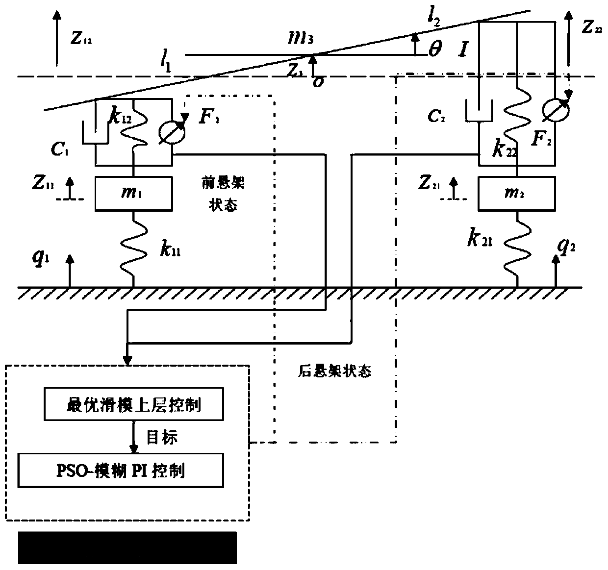
[0085] The present invention adopts half car 4 degrees of freedom vehicle model, see figure 1 , for dynamic analysis of the vehicle model:

[0086]

[0087]

[0088]

[0089]

[0090]

[0091] In the formula: z 21 ,z 22 are the vertical displacements of the connection points between the front and rear suspensions and the body, respectively; l 1 , l 2 are the distances from the body center of mass O to the front and rear axles; θ is the pitch angle; z 3 is the vertical displacement of the body center of mass; m 1 、m 2 、m 3 are the front and rear unsprung mass and sprung mass respectively; I is the pitch moment of inertia of the body around the center of mass; z 11 ,z 12 are the vertical displacements of the front and rear unsprung masses, respectively; c 1 、c 2 where is the e...

specific Embodiment approach 2

[0147] The sliding mode control method of the vehicle suspension described in this embodiment, on the basis of the specific embodiment 1, also includes the process of establishing a dynamic layered model to realize layered control, and the specific process is as follows:

[0148] Step 3. Establish a dynamic layered model:

[0149] The following is the analysis of the body force, figure 1 The bottom forces (including spring force, damping force, and semi-active actuator output force) of the front suspension system and rear suspension system in the formula are regarded as a concentrated force, that is, F f and F r ,Such as image 3 shown. According to the motion theorem of the center of mass and the theorem of the moment of momentum relative to the center of mass:

[0150]

[0151]

[0152] In the formula, m c is the sprung mass in kg; I c is the moment of inertia of the sprung mass, in kg m 2 ; is the displacement acceleration at the center of mass of the suspens...

Embodiment

[0216] Carry out control according to the mode of specific embodiment 1 and specific embodiment 2.

[0217] In the specific implementation mode 2, a semi-vehicle suspension can be decoupled into a combination of two 1 / 4 suspensions through the analysis of four parts. The specific design process of the optimal sliding mode layered control strategy is as follows:

[0218] (1) In the present invention, the suspension mass center acceleration obtained by optimal sliding mode control and pitch acceleration of the center of mass Multiplied by 0.6, respectively, as the target of the underlying control.

[0219] (2) Obtained from formulas (20), (21), (24) and (25) respectively and The estimated value of is obtained from formula (30), (31) and , and then get the estimated value of the decomposed front and rear suspension sprung mass acceleration:

[0220]

[0221]

[0222] (3) put and As a known value, establish Figure 5 The expression of the space state equatio...


PUM


Abstract

The invention discloses a sliding mode control method for a vehicle suspension and belongs to the field of vehicle control. The problem that when an existing control method is applied to a vehicle magneto-rheological suspension, the damping effect is not ideal is solved. The optimal control and the sliding mode control are combined to form the optimal sliding mode control based on the smoothness performance index, and the controller can determine the sliding mode switching surface equation according to the optimal control index, so that the system moves along the switching surface, and the system obtains the optimal performance and good variable working condition robustness. The suspension mass center acceleration and the mass center pitch angle acceleration which are obtained through optimal sliding mode control are further multiplied by corresponding coefficients to serve as targets of bottom layer control. Finally, the PSO-fuzzy PI is applied to the bottom layer control of the decoupling suspension, so that the hierarchical control of the magnetorheological suspension of the vehicle is realized, the control damping forces of the front suspension and the rear suspension are respectively obtained through the bottom layer control algorithm, and the control effect can be further improved. The method is used for controlling the vehicle suspension.

Description

technical field [0001] The invention relates to a control method of a vehicle. It belongs to the field of vehicle control. Background technique [0002] In recent years, research on the damping performance of the suspension system by means of control strategy has become a hot topic of research by scholars at home and abroad. According to different control methods, the suspension system with control function is divided into active control suspension system and semi-active control suspension system, thus breaking through the shock absorber mode of passive suspension system. Compared with the fully active control suspension, the semi-active control suspension does not require active energy input, but only needs to adjust the damping or spring stiffness of the control suspension system according to the requirements of the vehicle's driving conditions. It is safe, reliable, easy to implement, and has a very important Promote application value. [0003] The semi-active suspensi...

Claims


Application Information

Patent Timeline
Patent Type & Authority Applications(China)
IPC IPC(8): G06F17/50
CPCG06F30/15G06F2119/06
Inventor 张娜谢子殿苏勋文郭殿林邓孝祥任思璟
Owner HEILONGJIANG UNIVERSITY OF SCIENCE AND TECHNOLOGY
Why Eureka
Try Eureka