Rotating electrical machine

A technology for rotating electrical machines and rotors, applied to synchronous motors with stationary armatures and rotating magnets, electric components, electrical components, etc., can solve problems such as complex structures, achieve simplified structures, improve responsiveness, and improve maintainability Effect

Inactive Publication Date: 2019-08-06
HONDA MOTOR CO LTD
View PDF13 Cites 1 Cited by
  • Summary
  • Abstract
  • Description
  • Claims
  • Application Information

AI Technical Summary

Problems solved by technology

[0004] However, in the case of the above-mentioned structure of Patent Document 1, since the flow of the refrigerant is switched by the switching valve, there is a possibility that the structure may be complicated.

Method used


Image

  • Rotating electrical machine
  • Rotating electrical machine
  • Rotating electrical machine

Examples


no. 1 approach

[0032] [rotating motor]

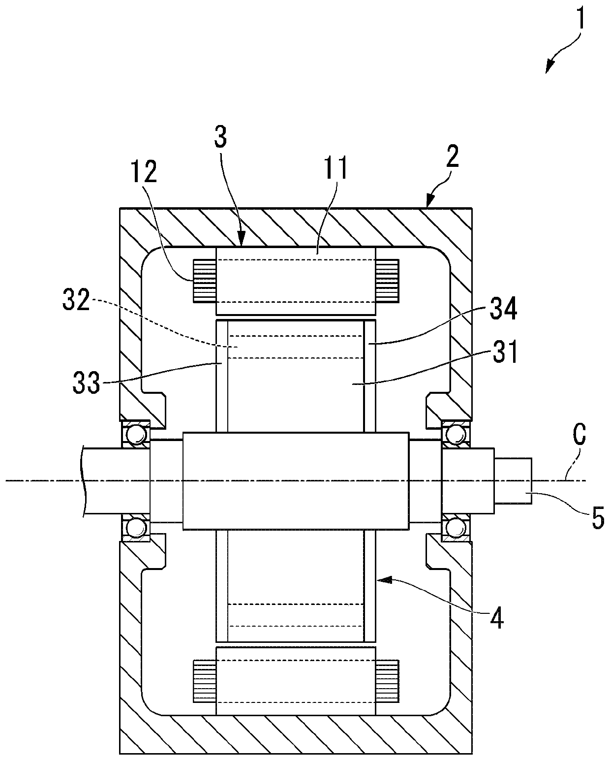
[0033] figure 1 It is a schematic configuration diagram (sectional view) showing the overall configuration of the rotating electric machine 1 of the first embodiment.

[0034] figure 1 The rotating electric machine 1 shown is, for example, a running motor mounted in a vehicle such as a hybrid vehicle or an electric vehicle. However, the configuration of the present invention is not limited to running motors, and may be applied to motors for power generation, motors for other purposes, and rotating electric machines (including generators) other than vehicles.

[0035] The rotating electrical machine 1 includes a housing 2, a stator 3, a rotor 4, an output shaft 5, and a refrigerant supply mechanism 6 (see figure 2 ).

[0036] The casing 2 accommodates a stator 3 , a rotor 4 and an output shaft 5 . A refrigerant (not shown) is accommodated in the casing 2 . The stator 3 is arranged in a state in which a part of the stator 3 is immersed in the ref...

no. 2 approach

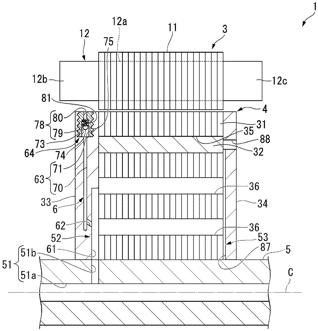
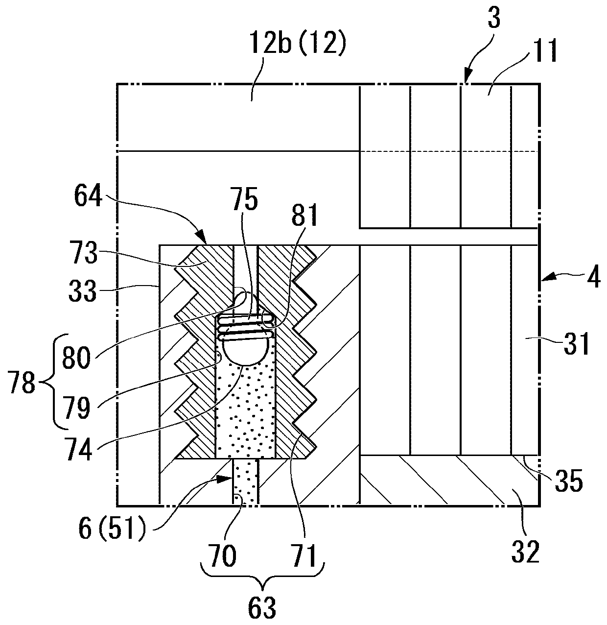
[0094] Next, a second embodiment of the present invention will be described. This embodiment differs from the above-described embodiment in that the opening and closing of the discharge port 80 is performed without using a biasing member. Figure 5 It is a partial sectional view of the rotating electric machine 1 of the second embodiment. In the following description, the same reference numerals are assigned to the same configurations as those of the above-mentioned first embodiment, and description thereof will be appropriately omitted.

[0095] exist Figure 5 In the rotary electric machine 1 shown, the stator supply flow path 63 is connected to the radially outer end portion of the rotor inlet flow path 61 . The radial outer end portion of the stator supply flow path 63 terminates at the outer peripheral portion of the first end plate 33 .

[0096] The discharge flow path 78 is connected to the radial outer end portion of the stator supply flow path 63 and extends in the...

no. 3 approach

[0103] Next, a third embodiment of the present invention will be described. This embodiment differs from the above-described embodiments in that the urging member 100 is formed in a leaf spring shape.

[0104] exist Figure 7 In the illustrated rotating electrical machine 1 , a urging member 100 is provided in the spool accommodating portion 79 . The urging member 100 is formed in the shape of a leaf spring extending in the radial direction. The radial inner end portion of the biasing member 100 is fixed to the first end panel 33 by the fixing member 101 .

[0105] That is, the urging member 100 is configured to be elastically deformable in the axial direction starting from the radial inner end portion. A weight portion 102 is provided at a radially outer end portion of the biasing member 100 .

[0106] The opposing surface of the inner surface of the spool accommodating portion 79 that faces the urging member 100 in the axial direction constitutes an abutment surface 110 ...


PUM


Abstract

A rotating electrical machine includes a tubular stator on which a coil is mounted, a rotor which is configured to be rotatable on an inner side in a radial direction with respect to the stator and has a rotor inner flow path through which a refrigerant can flow, and a refrigerant supply flow path which is provided in the rotor and through which a refrigerant flows from an inner side to an outer side in the radial direction as the rotor rotates. The refrigerant supply flow path includes a first flow path which communicates with the rotor inner flow path, and a second flow path which extends from the first flow path to an outer side in the radial direction and has a discharge port opening at an end portion in an axial direction of the rotor. A refrigerant adjustment section which adjusts adischarge amount of the refrigerant discharged from the discharge port by reducing an opening degree of the discharge port as a rotation speed of the rotor increases is provided in the second flow path.

Description

technical field [0001] This invention relates to rotating electric machines. Background technique [0002] In a rotating electric machine mounted on a hybrid vehicle, an electric vehicle, etc., a magnetic field is formed in a stator core by supplying current to a coil, and magnetic attraction and reaction force are generated between the permanent magnets of the rotor and the stator core. Thus, the rotor rotates relative to the stator. [0003] However, in a rotating electrical machine, since copper loss increases in a high torque state, the coil tends to generate heat easily. On the other hand, since iron loss increases at high rotational speeds, the rotor core, stator core, etc. tend to generate heat easily. Then, for example, Japanese Patent Application Laid-Open No. 2008-263753 (hereinafter referred to as Patent Document 1) discloses a system including a first supply pipe for supplying a large amount of refrigerant to a coil and a device for supplying a large amount of ...

Claims


Application Information

Patent Timeline
Patent Type & Authority Applications(China)
IPC IPC(8): H02K1/32
CPCH02K1/32H02K9/19H02K5/1732H02K21/16H02K21/14
Inventor 梶川薰
Owner HONDA MOTOR CO LTD
Why Eureka
Try Eureka