Construction method of sewage pipeline

A construction method and technology of sewage pipelines, applied in the field of pipelines, can solve the problems of low efficiency of sewage pipelines, etc., and achieve the effects of improving construction efficiency, improving compressive strength, and improving physical properties

Active Publication Date: 2019-08-09
广东隆建工程有限公司
View PDF7 Cites 5 Cited by
  • Summary
  • Abstract
  • Description
  • Claims
  • Application Information

AI Technical Summary

Problems solved by technology

[0004] However, the pipe jacking process needs to overcome a large amount of friction, which makes the construction efficiency of the sewage pipeline low, so there is still room for improvement

Method used


Image

  • Construction method of sewage pipeline

Examples


Embodiment 1

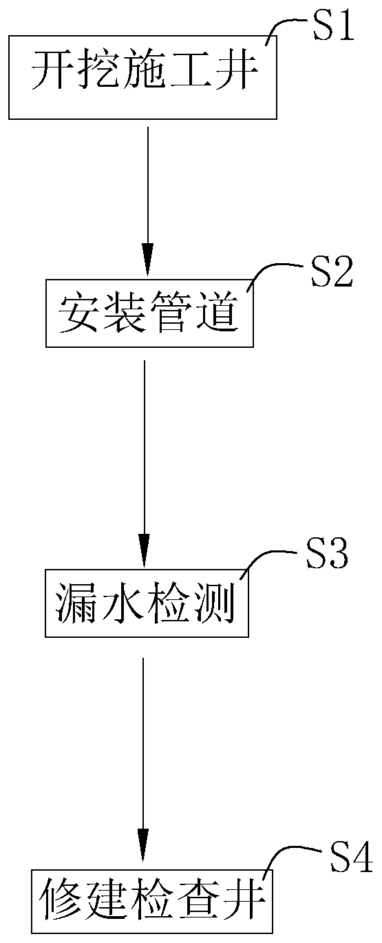
[0050] A kind of sewage pipeline construction method, with reference to figure 1 , including the following steps:

[0051] S1. Excavation of construction wells, details are as follows:

[0052] Position according to the position of the inspection well in the design drawings, and excavate the construction well, and start the next step after excavating at least two adjacent construction wells.

[0053] S2. Install the pipeline, as follows:

[0054] Drill the hole with the drilling rig, excavate the soil with the excavator and transport the soil damaged by the drilling rig out of the hole in time to drill the sewage pipe installation hole on the side wall of the construction well and remove the excavated soil in time;

[0055] The inner diameter of the sewage pipe installation hole is 10mm larger than the inner diameter of the sewage pipe in the design. After drilling for 1m, clean the inner wall of the pipe and spray the sewage pipe composition to form the pipe wall of the sew...

Embodiment 2

[0063] The difference from Example 1 is that

[0064] In step S2:

[0065] The inner diameter of the sewage pipe installation hole is 15mm larger than the inner diameter of the sewage pipe in the design. After drilling for 2.5m, clean the inner wall of the pipe and spray the sewage pipe composition to form the pipe wall of the sewage pipe;

[0066]When spraying, first add the sewage pipe composition into the extrusion equipment and heat it to 240°C, then extrude and spray on the inner wall of the sewage pipe installation hole through the nozzle, and the spray thickness is 15mm;

Embodiment 3

[0068] The difference from Example 1 is that

[0069] In step S2:

[0070] The inner diameter of the sewage pipe installation hole is 18mm larger than the inner diameter of the sewage pipe in the design. After drilling for 5m, clean the inner wall of the pipe and spray the sewage pipe composition to form the pipe wall of the sewage pipe;

[0071] When spraying, first add the sewage pipe composition into the extrusion equipment and heat it to 260°C, then extrude and spray on the inner wall of the sewage pipe installation hole through the nozzle, and the spray thickness is 18mm;


PUM

PropertyMeasurementUnit
thicknessaaaaaaaaaa
particle diameteraaaaaaaaaa
lengthaaaaaaaaaa

Abstract

The invention relates to the technical field of pipelines, and provides a construction method of a sewage pipeline in order to solving the problem of low efficiency during water pipeline construction.According to the technical scheme, the construction method of the sewage pipeline comprises the following steps that S1, construction wells are excavated; S2, the pipeline is installed, specifically,sewage pipe installing holes communicating adjacent construction wells are formed by drilling through a drilling machine, advancing is carried out for every 1-5 m and is stopped when drilling is carried out, and sewage pipe mixtures are sprayed to the hole walls to form the pipe wall of a sewage pipe; S3, water leakage detection is carried out, specifically, the sewage pipe mixtures are sprayed to the water leakage positions for leak repairing according to the detection results; and S4, an inspection well is constructed. The sewage pipe installing holes are drilled, the sewage pipe mixtures are sprayed to the hole walls to form the pipe wall of the sewage pipe at the same time, so that drilling and pipeline preparation are carried out synchronously, soil frictional force does not need tobe overcome, and the construction efficiency of the sewage pipe is greatly improved.

Description

technical field [0001] The invention relates to the technical field of pipelines, in particular to a sewage pipeline construction method. Background technique [0002] The sewage pipe network is one of the important means of urban sewage discharge, and the most important part of laying the sewage pipe network is the laying of underground sewage pipes. [0003] Generally speaking, the pipe jacking process is usually used when laying sewage pipes, because the pipe jacking process can effectively reduce the occupation of the road surface and reduce the impact on traffic. [0004] However, the pipe jacking process needs to overcome a large amount of friction, which makes the construction efficiency of the sewage pipeline low, so there is still room for improvement. Contents of the invention [0005] In view of the deficiencies in the prior art, the purpose of the present invention is to provide a sewage pipeline construction method, which has the advantage of high constructio...

Claims


Application Information

Patent Timeline
Patent Type & Authority Applications(China)
IPC IPC(8): E03F3/06E03F3/04C08L59/00C08L33/20C08L77/00
CPCC08L59/00C08L2203/18C08L2205/03E03F3/04E03F3/06C08L33/20C08L77/00
Inventor 黄涛胡绵雄李丽萍
Owner 广东隆建工程有限公司
Why Eureka
Try Eureka