
Solar power transmission tower

A transmission tower and solar energy technology, applied in the field of transmission towers, can solve problems such as power supply failure, threat to the operation safety of transmission towers, and freezing of transmission towers, and achieve the effects of improving power generation efficiency, ensuring normal light-receiving power generation, and reducing the risk of overload collapse.

Inactive Publication Date: 2019-08-09
MINJIANG UNIV +1
View PDF10 Cites 3 Cited by
  • Summary
  • Abstract
  • Description
  • Claims
  • Application Information

AI Technical Summary

Problems solved by technology

[0003] At present, when carrying out long-distance transmission of electric energy, it is mainly to rely on transmission towers with large metal frame structures to erect transmission lines in the air. The reason is that it is very easy to cause icing on the surface of the transmission tower. When the amount of icing is too large, it is easy to threaten the operation safety of the transmission tower, and even cause the transmission tower to collapse in severe cases, resulting in serious power failure.

Method used


Image

  • Solar power transmission tower
  • Solar power transmission tower
  • Solar power transmission tower

Examples


Embodiment Construction

[0029] In order to make the purpose, technical solutions and advantages of the embodiments of the present invention clearer, the technical solutions in the embodiments of the present invention will be clearly and completely described below in conjunction with the accompanying drawings in the embodiments of the present invention. Obviously, the described embodiments It is some embodiments of the present invention, but not all of them. Based on the implementation manners in the present invention, all other implementation manners obtained by persons of ordinary skill in the art without creative efforts fall within the protection scope of the present invention. Accordingly, the following detailed description of the embodiments of the invention provided in the accompanying drawings is not intended to limit the scope of the claimed invention, but merely represents selected embodiments of the invention. Based on the implementation manners in the present invention, all other implement...


PUM


Abstract

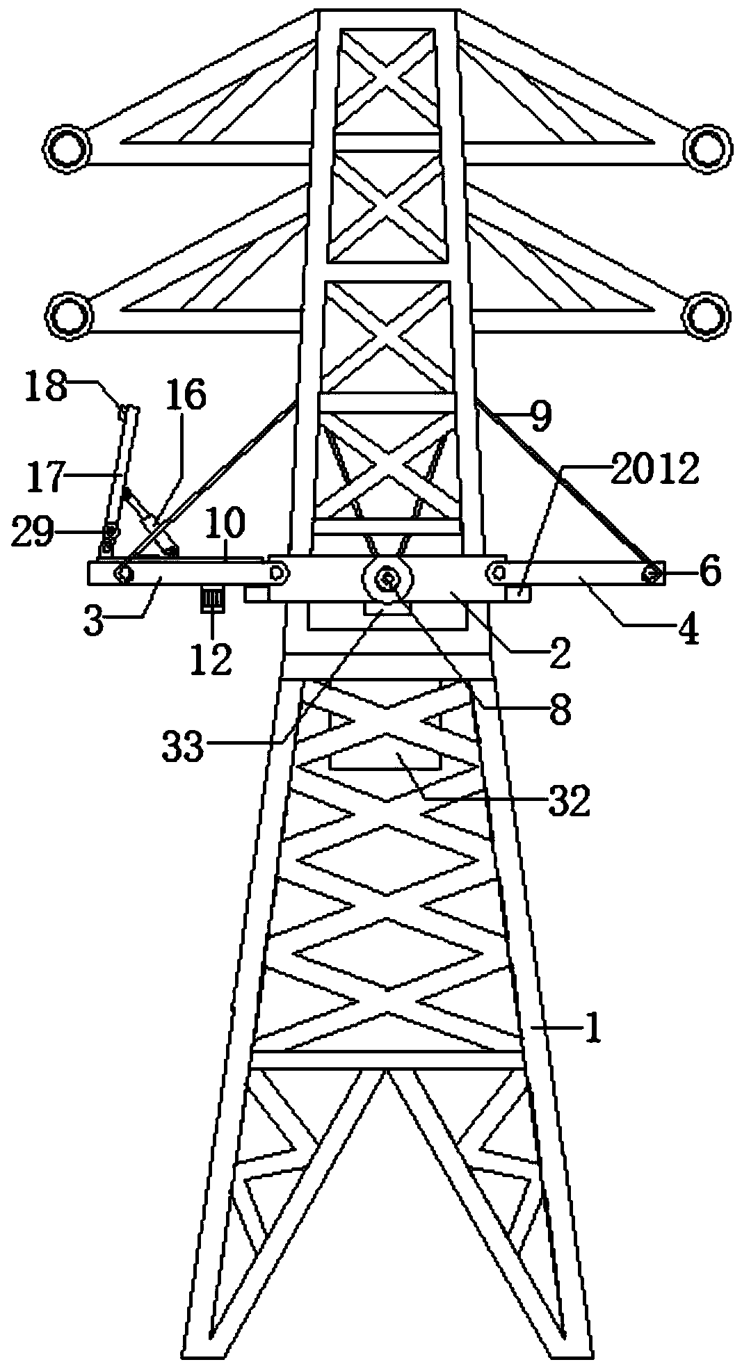
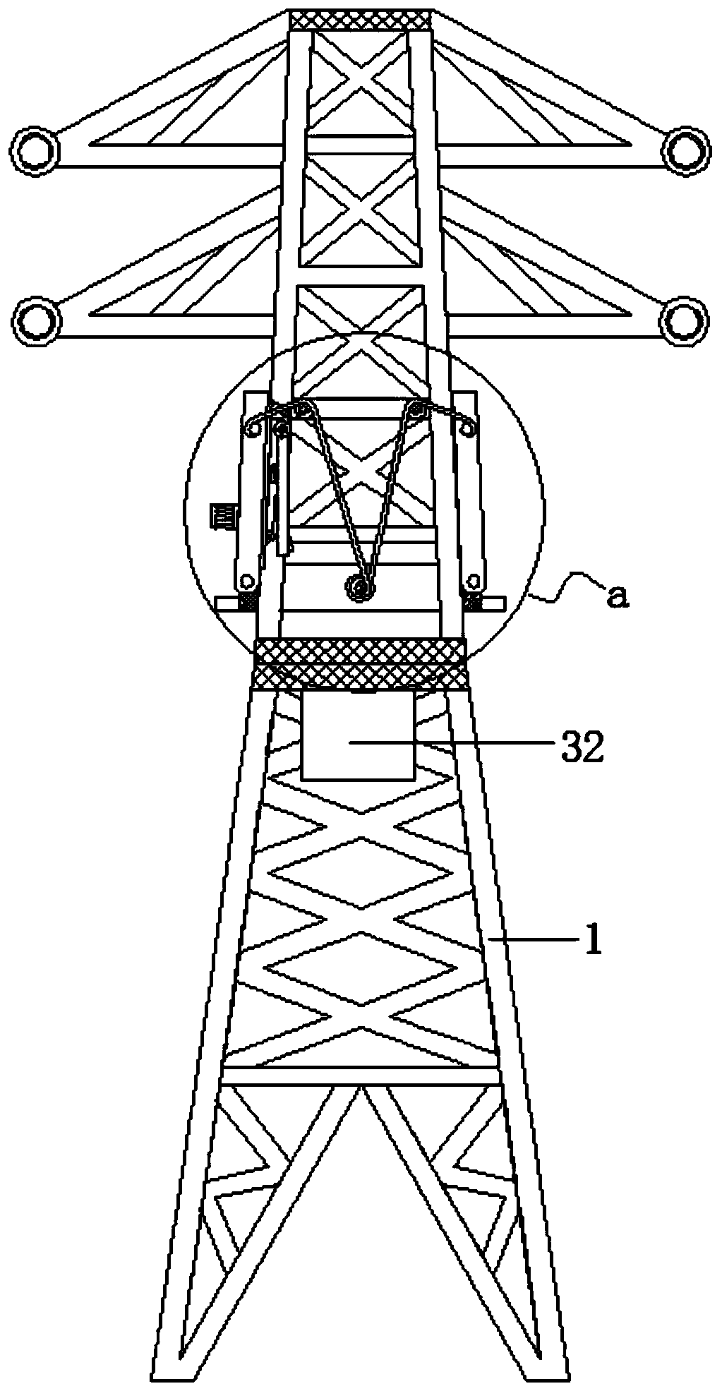
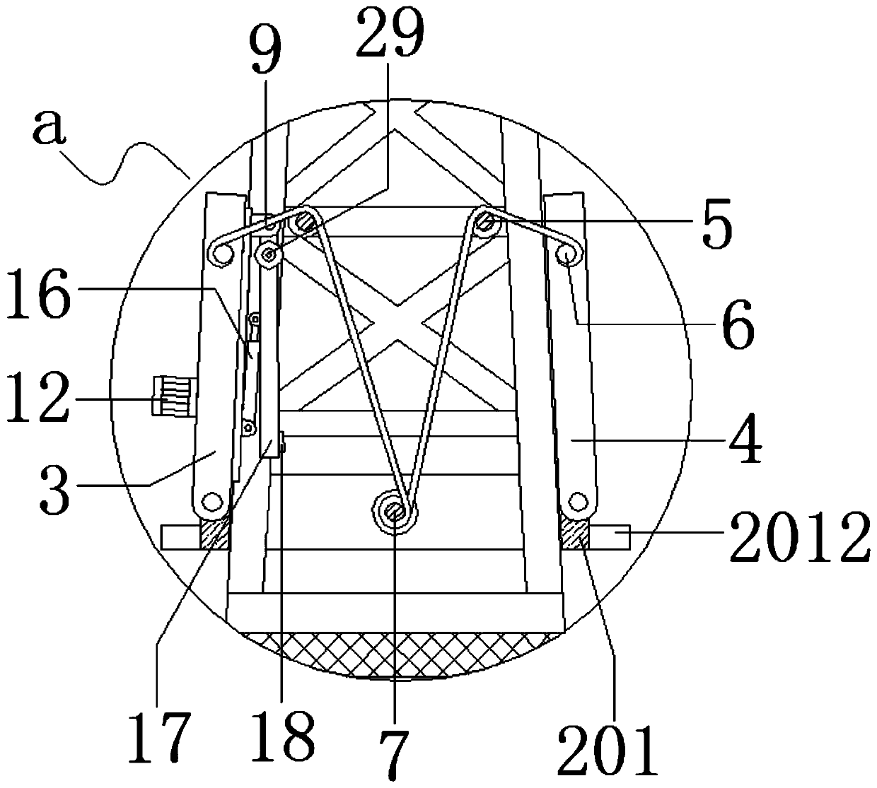
The invention relates to the technical field of power transmission towers, in particular to a solar power transmission tower. The solar power transmission tower comprises a tower body; a frame body isarranged in the middle of the tower body, and a movable plate and a loading plate are hinged to the left side and the right side of the frame body correspondingly; a set of steering wheels is arranged above the loading plate, and the steering wheels are fixed to the tower body; fixed columns are fixedly connected to the front side walls and the rear side walls, close to the tail ends, of the movable plate and the loading plate correspondingly; the middle of the frame body is rotationally connected with a winding roller, and a first motor is arranged on the front side of the frame body; the first motor drives the winding roller to rotate through a reduction gear box, and ropes are connected to the fixed columns correspondingly; the ropes on the two sides are wound across the steering wheels and wound on the winding roller in the same direction; and a circular groove is formed in the top of the movable plate, and a circular rotary table is rotationally connected into the circular groovein the top of the movable plate. The solar power transmission tower can prevent accumulation of frost on the electric tower and lower the risk that the electric tower is overloaded and then collapses, can further guarantee normal light receiving power generation of a solar cell panel, and is suitable for being further used and popularized.

Description

technical field [0001] The invention relates to the technical field of power transmission towers, in particular to a solar power transmission tower. Background technique [0002] Electric towers are trapezoidal or triangular tower-shaped buildings, usually 25-40 meters high, and are steel frame structures. Electric towers are mostly built near power plants and distribution stations in the field. It is an important facility in the power sector, which can overhead wires and play a role in protection and support. The design, manufacture, installation, maintenance and quality inspection of power towers are important guarantees for the operation and development of modern power systems. [0003] At present, when carrying out long-distance transmission of electric energy, the transmission line is mainly suspended by the transmission tower with a large metal frame structure. The reason is that it is very easy to cause icing on the surface of the transmission tower. When the amount...

Claims


Application Information

Patent Timeline
Patent Type & Authority Applications(China)
IPC IPC(8): E04H12/10H02S20/32H02S40/12
CPCE04H12/10H02S20/32H02S40/12Y02E10/50
Inventor 邵振华林文忠张祖昌
Owner MINJIANG UNIV
Learn More