
Method and system for detection and localization of specific region boundary for samples with complex components

A specific area and boundary detection technology, applied in the direction of color/spectral property measurement, measurement device, analysis material, etc., to achieve the effect of high sensitivity, deep penetration depth, and shortened operation time

Active Publication Date: 2022-04-05
TONGJI UNIV
View PDF2 Cites 0 Cited by
  • Summary
  • Abstract
  • Description
  • Claims
  • Application Information

AI Technical Summary

Problems solved by technology

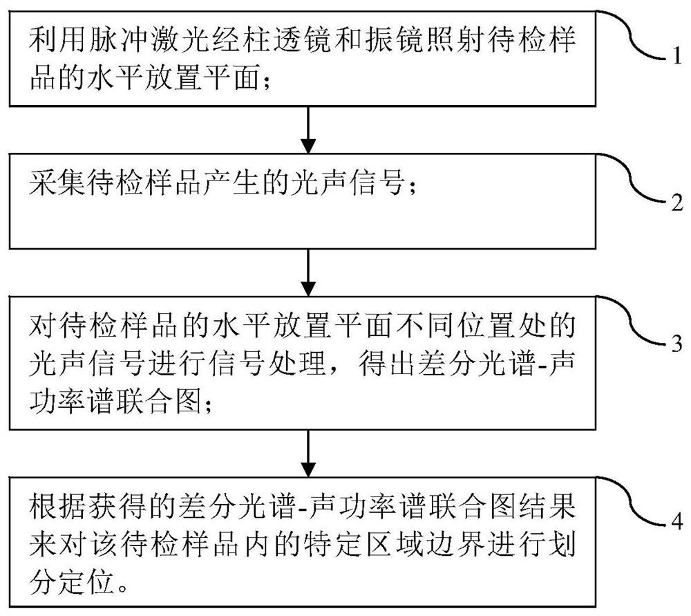
[0004] The purpose of the present invention is to provide a specific area boundary detection and positioning method and system for complex component samples in order to overcome the above-mentioned defects in the prior art, aiming at the existing boundary detection and positioning technology can only be determined from a physical point Due to the limitation of the boundary detection and positioning of the specific area of ​​the sample, a method is proposed to analyze the tissue components from the chemical molecular level to determine the properties of the tissue, and compare the differences between different positions in the specific area of ​​​​the horizontal plane of the sample to be tested and the reference tissue through differential calculation. The difference spectrum-acoustic power spectrum joint map can distinguish the molecular chemistry, microstructure and other information of adjacent tissue regions, so as to achieve the purpose of boundary calibration

Method used


Image

  • Method and system for detection and localization of specific region boundary for samples with complex components
  • Method and system for detection and localization of specific region boundary for samples with complex components
  • Method and system for detection and localization of specific region boundary for samples with complex components

Examples


Embodiment

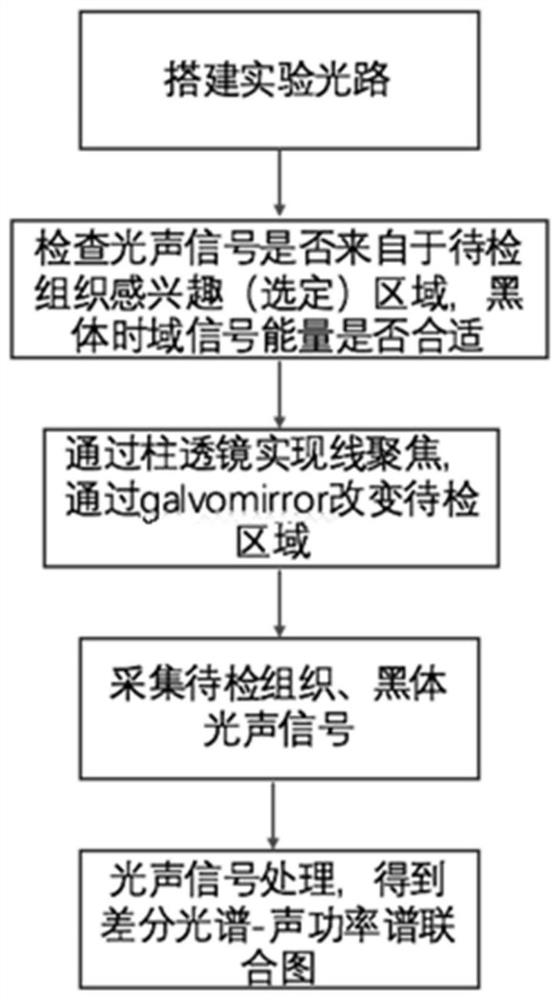
[0036] Such as image 3 Shown is the schematic flow chart of the method corresponding to the embodiment of the technical solution of the present invention, including the following steps:

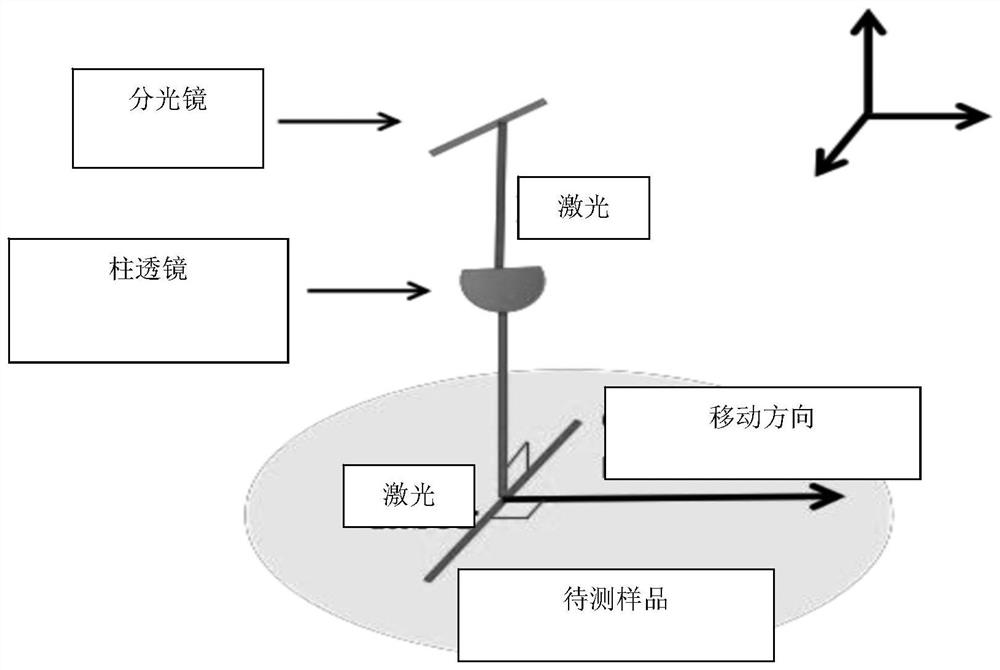
[0037] Step 1, build the optical path, realize line focusing on the horizontal plane of the sample to be tested and collect photoacoustic signals, the pulsed laser passes through the galvomirror and the cylindrical lens and irradiates vertically on a specific area (XY plane) of the horizontal plane of the sample to be tested, where the Y direction is The needle hydrophone is placed horizontally.

[0038] Step 2, prepare the water tank, black tape, place the transducer in the water and align it with the blackbody position, receive the blackbody signal, and use it as laser energy normalization to eliminate instrument interference;

[0039] Step 3, collecting the photoacoustic signal generated by the sample to be tested includes the following steps:

[0040] In the sample to be tested, a norm...


PUM


Abstract

The invention relates to a specific area boundary detection and positioning method and system for samples with complex components, which specifically includes: shaping the outgoing laser, and the cylindrical laser shaped by the cylindrical lens is vertically irradiated on the horizontal plane of the sample; Change the position where the columnar laser is irradiated on the horizontal plane of the sample to be tested, collect the photoacoustic signal, and through signal processing, the combined spectrum-acoustic power spectrum at the position of the sample to be tested can be obtained, and the joint difference spectrum-acoustic power spectrum can be obtained The amplitude of the sound power spectrum after normalizing the upper energy can determine the molecular chemistry, microstructure and other information at the position of the sample to be inspected, and then perform boundary detection and positioning. The system includes a pulsed laser source, a glass slide, a needle hydrophone, an amplifier, Oscilloscope, cylindrical lens, galvomirror and computer; the present invention aims at the problem that current medical equipment can only perform boundary detection, location and distinction from a physical point of view, and proposes a new boundary detection scheme, which has the dual advantages of high sensitivity and deep penetration depth.

Description

technical field [0001] The invention relates to the technical field of medical equipment, in particular to a method and system for boundary detection and positioning of a specific area for complex component samples. Background technique [0002] One of the main reasons for the postoperative survival rate is that not all the tissue in a specific area was removed during the operation, resulting in residual positive margins. [0003] With the development of the times, how to achieve accurate and rapid identification of boundaries in specific regions during surgery has become a common goal in the medical field. At present, the existing new technologies for intraoperative auxiliary calibration of boundaries include: intraoperative ultrasound assistance, intraoperative CT, intraoperative In MRI, etc., the above technologies have their own advantages and disadvantages. They are unable to distinguish tissues with similar physical properties but different chemical properties. A metho...

Claims


Application Information

Patent Timeline
Patent Type & Authority Patents(China)
IPC IPC(8): G01N21/31G01N21/17
CPCG01N21/31G01N21/1702G01N2021/3125G01N2021/1757
Inventor 程茜吴诗颖陈盈娜潘晶封婷张浩南解维娅张梦娇
Owner TONGJI UNIV
Learn More