Light radiator and light shielding member

A technology of light irradiation and light shading, applied in phototherapy, radiation therapy, treatment, etc., can solve the problems of high price, unreasonable posture, and difficulty in irradiating uniform irradiation intensity therapeutic light, etc., to achieve the effect of preventing light irradiation

Active Publication Date: 2019-08-09
SHARP KK
View PDF12 Cites 1 Cited by
  • Summary
  • Abstract
  • Description
  • Claims
  • Application Information

AI Technical Summary

Problems solved by technology

[0009] In addition, the patient needs to maintain a long-term motionless posture while constraining the body for treatment, which puts an excessive load on the body and feels fatigue
Moreover, when the affected part has a curved surface, such as a part of an arm or a part of a foot, any of the front side, rear side, or side of the part can be treated with a device using a lamp-type light source. Partially irradiated, forcing the patient into unreasonable positions
[0010] In addition, depending on the angle and distance of the affected part having a curved surface from the device using the lamp-type light source, the irradiation intensity varies for each part constituting the affected part, so it may be difficult to uniformly irradiate the affected part as a whole. The intensity of the treatment light in the case of the irradiation
In addition, a device using a lamp-type light source requires a large space for installation and is also expensive due to the large number of accessories such as a power supply and a cooling device.

Method used


Image

  • Light radiator and light shielding member
  • Light radiator and light shielding member
  • Light radiator and light shielding member

Examples


no. 1 approach 〕

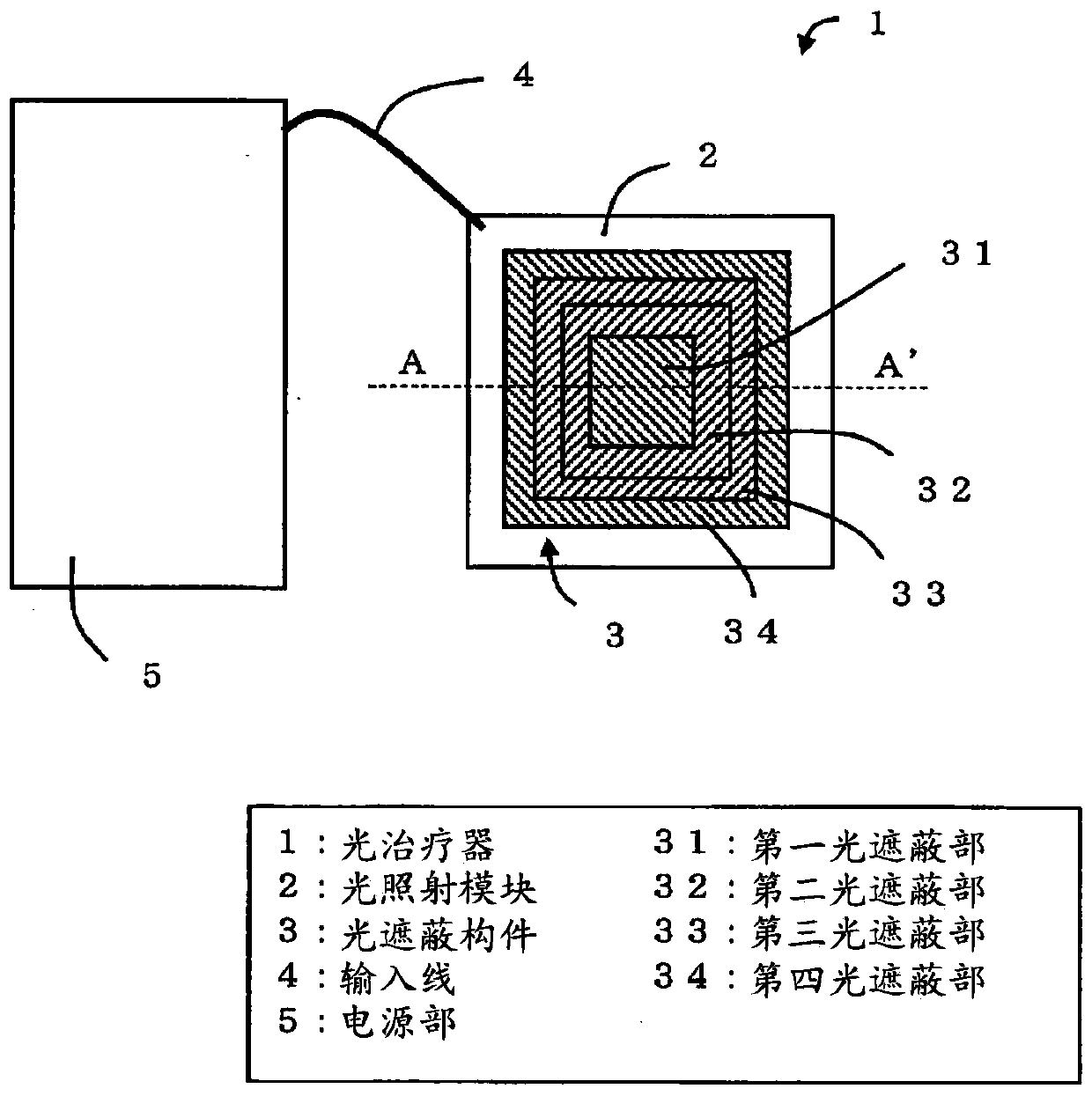
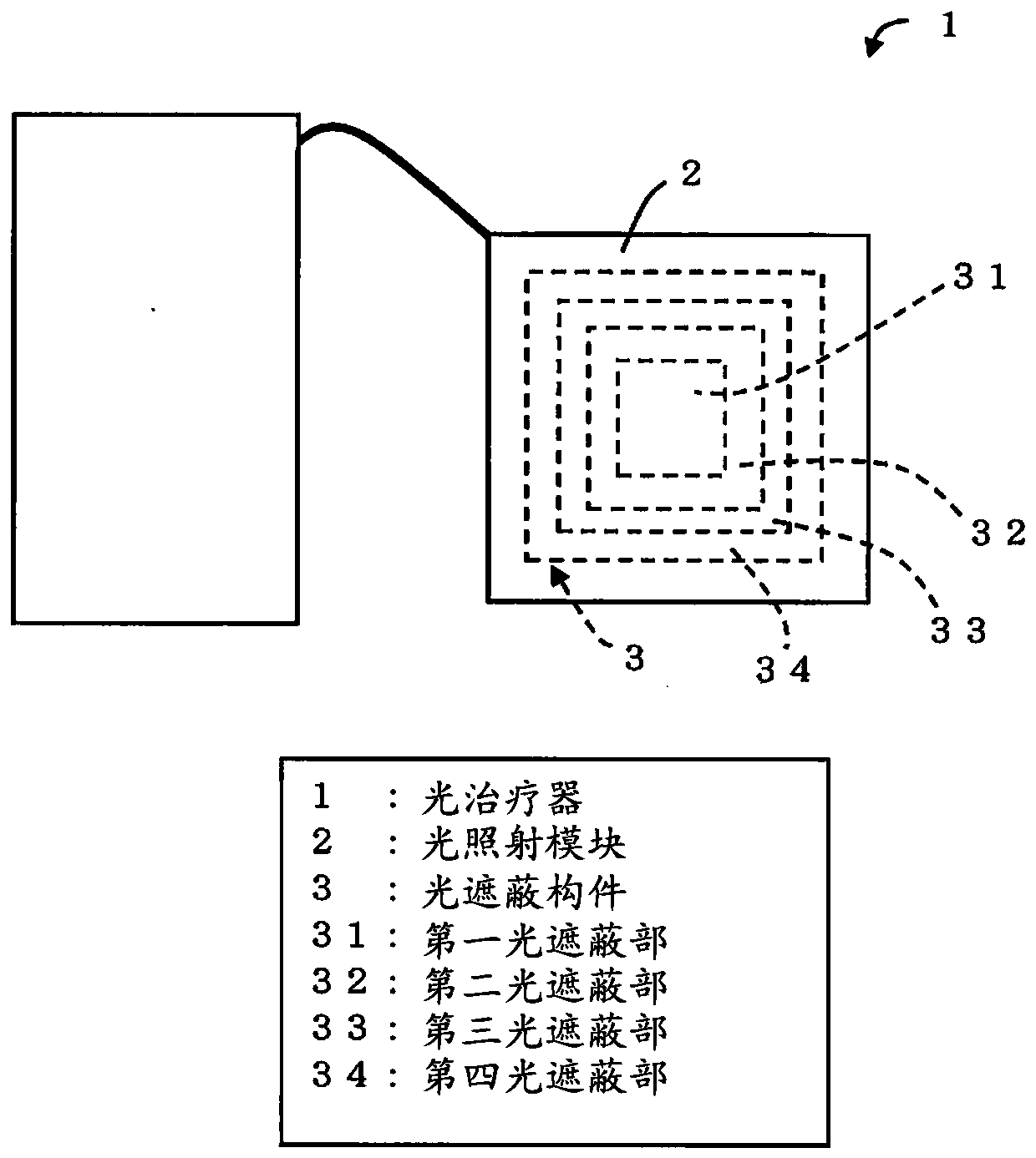
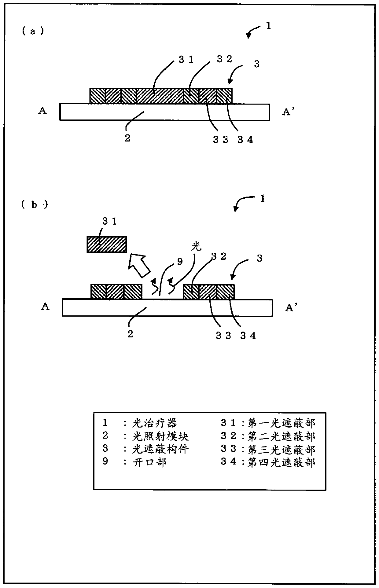
[0058] based on Figure 1 to Figure 5 , Figure 17 to Figure 20 One embodiment of the present invention will be described as follows. Hereinafter, the LED chip 14 mounted in the light irradiation module 2 (light source: refer to Figure 17 ) as the front surface, and the surface opposite to the surface on which the LED chip 14 is mounted is the back surface.

[0059] In addition, if Figure 17 As shown, in the flexible substrate 15 (substrate), a plurality of LED mounting regions 17 on which the LED chips 14 are mounted are formed in a lattice shape in plan view. Two adjacent LED mounting regions 17 are insulated, and the two LED mounting regions 17 are connected by wiring 16 . In addition, wire bonding connections are also included in the wiring 16 .

[0060] Here, use Figure 18 The positions of the light shielding member 3 and the LED chip 14 in the phototherapy device 1 (photoirradiator) according to the first embodiment of the present invention will be described. S...

no. 2 approach 〕

[0097] based on Image 6 Other embodiments of the present invention will be described below. In addition, for convenience of description, members having the same functions as those described in the above-described embodiments are given the same reference numerals, and descriptions thereof are omitted. In addition, in this embodiment, the shape of the light shielding member 3a is demonstrated especially about the difference from 1st Embodiment. Image 6 (a)-(e) is a schematic diagram which shows each example of the light shielding member 3a which comprises the phototherapy device 1a which concerns on 2nd Embodiment of this invention. In addition, since the light shielding member 3 of the phototherapy device 1 is replaced with the light shielding member 3a in the phototherapy device 1a, it is not shown in figure.

[0098]

[0099] refer to Image 6 (a) to (e) describe an example of the shape of the light shielding member 3 a constituting the phototherapy device 1 a accordin...

no. 3 approach 〕

[0109] based on Figure 7 to Figure 10 Other embodiments of the present invention will be described below. In addition, for convenience of description, members having the same functions as those described in the above-described embodiments are given the same reference numerals, and descriptions thereof are omitted. In addition, in this embodiment, the structure of the phototherapy device 1b and the shape of the light shielding member 3b are demonstrated especially about the difference from 1st Embodiment and 2nd Embodiment.

[0110]

[0111] refer to Figure 7 to Figure 10 , the structure of the phototherapy device 1b according to the third embodiment of the present invention will be described. Figure 7 It is a schematic diagram showing the structure of the surface of the phototherapy device 1b. Figure 8 It is a schematic diagram showing the structure of the back surface of the phototherapy device 1b. Figure 9 It is a schematic cross-sectional view showing a first exa...


PUM

PropertyMeasurementUnit
transmittivityaaaaaaaaaa

Abstract

The objective of the present invention is to carry out radiation of light onto a desired region of the skin reliably and simply, while preventing radiation of light onto regions other than the desiredregion. A light radiator (1) is provided with: a light source which radiates light onto skin; a light shielding member (3) disposed between the skin and the light source; and a flexible base on whichthe light source and the light shielding member (3) are mounted; wherein an opening portion (9) corresponding to a specific region (8) of the skin can be formed in the light shielding member (3), andlight is radiated onto the specific region through the opening portion (9).

Description

technical field [0001] The present invention relates to a photoirradiator and a photoshielding member used for photoirradiation therapy, beauty and hairdressing, and the like. Background technique [0002] Photodynamic therapy (Photo Dynamic Therapy; PDT) is a chemical reaction caused by irradiating light of a specific wavelength to a photosensitive substance that has an affinity for abnormal cells and tumors to generate active oxygen, etc. Treatment of tumor necrosis. Starting from a therapeutic method that does not damage normal cells, the viewpoint of QOL (Quality Of Life) has recently attracted much attention. [0003] PDT is used for various purposes such as treatment of diseases such as neonatal jaundice, psoriasis, and acne, pain relief, and beauty and hairdressing. Acne treatments use blue, red, and yellow lights. In this way, when performing PDT, a light source that irradiates light of an appropriate wavelength is used depending on the purpose of treatment. [0...

Claims


Application Information

Patent Timeline
Patent Type & Authority Applications(China)
IPC IPC(8): A61N5/06
CPCA61N5/0616A61N2005/005A61N2005/0666A61N2005/0667A61N5/062A61N2005/0651A61N2005/0658
Inventor 森淳青木仁志前川真澄
Owner SHARP KK
Why Eureka
Try Eureka