A multi-slug step-by-step plugging method suitable for fractured formations

A plugging method and multi-slug technology, applied in the field of oil and gas field exploration and development, can solve problems such as cost increase, plugging particle waste, plugging layer damage, etc., to save facility costs, save plugging costs, and good plugging quality Effect

Active Publication Date: 2020-05-05
SOUTHWEST PETROLEUM UNIV
View PDF6 Cites 0 Cited by
  • Summary
  • Abstract
  • Description
  • Claims
  • Application Information

AI Technical Summary

Problems solved by technology

[0003] (1) Changes in wellbore fluid column pressure will cause dynamic deformation of formation fractures, which will change the position, plugging state, and pressure bearing capacity of the original effective sealing layer, which may cause damage to the sealing layer, resulting in repeated leakage;
[0004] (2) Plugging particles of different particle sizes are mixed in the plugging working fluid. Before a tight seal is formed, some small-sized particles will leak into the formation through the gap between the fracture channel and the large-sized particles, resulting in the loss of plugging particles. waste, which increases costs;
[0005] (3) For fractured reservoirs, fractures are the main flow channels for oil and gas migration, so the production of fractured reservoirs is much higher than that of other reservoirs, and during the drilling plugging process, the lost plugging particles enter the formation through fractures Throats block the channels for oil and gas production, greatly reducing production and causing solid particle intrusion damage

Method used


Image

  • A multi-slug step-by-step plugging method suitable for fractured formations
  • A multi-slug step-by-step plugging method suitable for fractured formations
  • A multi-slug step-by-step plugging method suitable for fractured formations

Examples


Embodiment Construction

[0032] The present invention will be further described below according to the accompanying drawings, so that those skilled in the art can understand the present invention. However, it should be clear that the present invention is not limited to the scope of specific implementations. For those of ordinary skill in the art, as long as various changes are within the spirit and scope of the present invention defined and determined by the appended claims, they are all within the scope of protection. List.

[0033] see figure 1 , figure 2 .

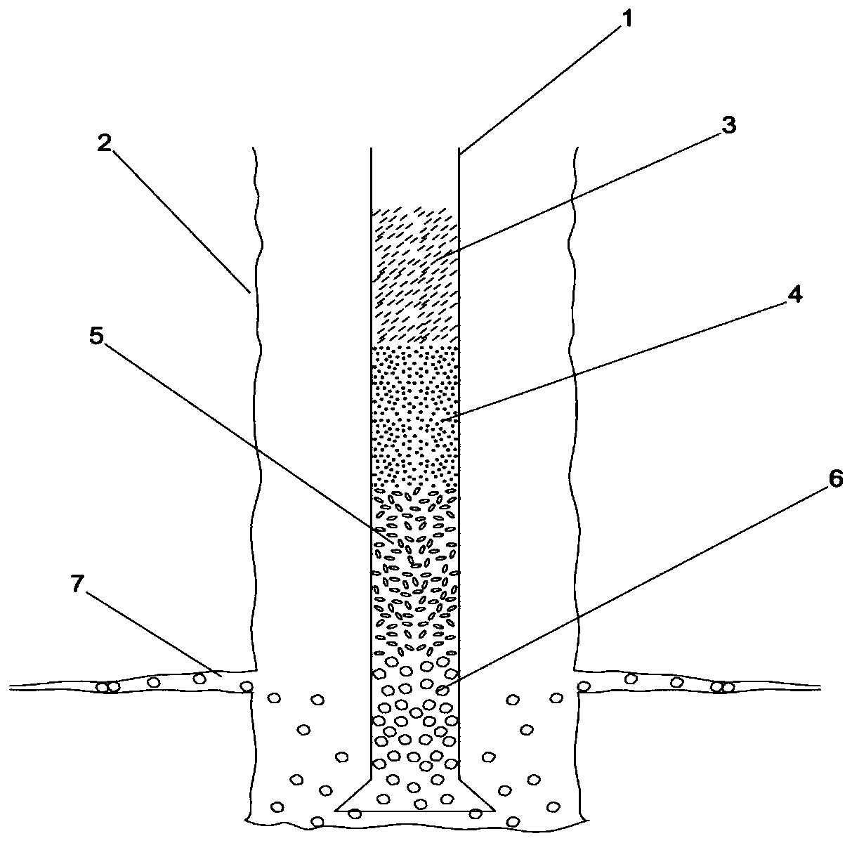
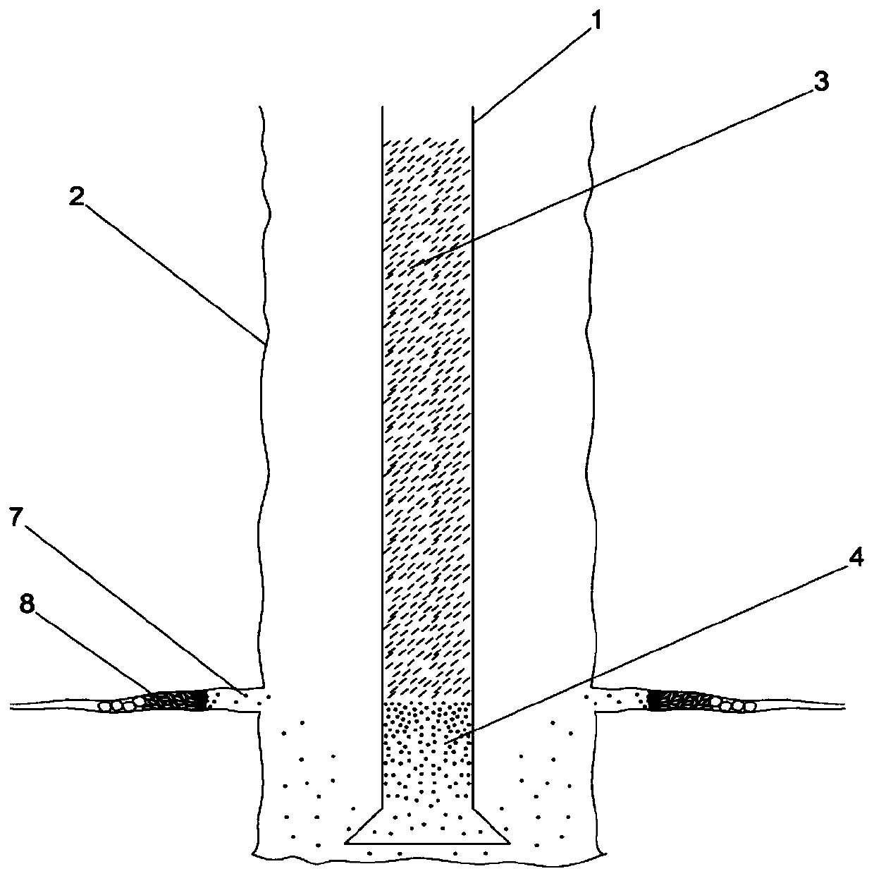
[0034] figure 1 , figure 2 It is a schematic diagram of the flow before and after plugging using the multi-slug staged plugging method. During the drilling process, the drill pipe 1 is located in the center of the well wall 2, and the drilling fluid 3 enters the bottom of the well through the drill pipe 1, and then flows through the annulus between the drill pipe 1 and the well wall 2 and returns to the ground. When the formation is dri...


PUM

PropertyMeasurementUnit
particle sizeaaaaaaaaaa

Abstract

The present invention relates to a multi-slug staged plugging method suitable for fractured formations, comprising: step 1) determining the average opening of the fractures around the well as D, and using bridging particles with a particle size slightly smaller than D in the first-stage plugging. The average particle size is expressed as D 1 , the average particle size D of the plugging particles is used for the secondary plugging 2 greater than D 1 / 4, and less than D 1 , use the same method to determine the particle size of the following plugging particles in sequence, until the average particle size of the last stage of plugging particles is D n Small enough to form a tight plugging layer; step 2) first inject through the slug containing only 1 The plugging slurry of bridging particles forms a layer of bridging particles; step 3) injects the plugging particles with an average particle size of D through multiple slugs 2 ~D n‑1 plugging slurry to form a particle packing layer; step 4) use a slug to finally inject a plugging slurry with an average particle size of plugging particles Dn to form a tight sealing layer. The invention has a reliable principle, more effectively seals the cracks around wells, saves costs, and has broad application prospects.

Description

technical field [0001] The invention relates to a multi-segment staged leak plugging method suitable for fractured formations in drilling plugging operations in the field of oil and gas field exploration and development. Background technique [0002] When severe drilling fluid loss occurs in the drilling process of petroleum engineering, it is often caused by natural fractures in the well or induced fractures caused by bottomhole pressure. In order to eliminate or reduce the loss, it is necessary to seal the fractures around the well according to the actual engineering situation. The usual practice is to add plugging materials of different particle sizes and types to the drilling fluid according to the amount of leakage and the location of the leakage, and then inject it downhole at one time to seal the fractures around the well. The basic principle of the formation of plugging is that larger-sized particles form a bridge in the narrow part of the fracture, which narrows the...

Claims


Application Information

Patent Timeline
Patent Type & Authority Patents(China)
IPC IPC(8): E21B33/13
CPCE21B33/13C04B28/10C04B30/02C09K8/426C09K8/467C09K2208/04C09K2208/08C09K2208/18Y02W30/91C04B14/20C04B14/28C04B18/20C04B18/22C04B18/248C04B14/104C04B18/24C04B18/18C04B26/26C09K8/44E21B33/134E21B33/138E21B49/00
Inventor 李皋李睿冯一
Owner SOUTHWEST PETROLEUM UNIV
Why Eureka
Try Eureka