Current transformer trailing current identification algorithm based on waveform characteristic difference

A current transformer and tailing current technology, which is applied in the field of current transformer tailing current identification algorithm, can solve the problems of power system influence, long identification time, misjudgment of time constant protection, etc., and achieve strong engineering practicability and electrical quantity Less information, good anti-interference effect

Active Publication Date: 2019-08-13
CHINA THREE GORGES UNIV
View PDF10 Cites 4 Cited by
  • Summary
  • Abstract
  • Description
  • Claims
  • Application Information

AI Technical Summary

Problems solved by technology

[0003] When the initial current amplitude of the trailing current is high and the time constant of the secondary side of the CT is large, some protection misjudgments may be caused, such as circuit breaker failure, expanding the scope of power outages, and having a greater impact on the power system (Jiang Ziqiang , Liu Jianyong. Research on Failure Protection of Nanyang UHV Circuit Breaker[J]. Power System Protection and Control, 2015, 43(12): 117-122.)
[0004] At present, for the identification method of tailing current, it is generally to detect the zero-crossing point of the waveform, which requires a cycle of time, and the identification time is relatively long. In addition, once the non-periodic bias current in the fault current is too large, the fault current waveform will be in the One cycle or even a longer period of time will not cross the zero point, and the transmission error of the CT device may also cause the zero-crossing phenomenon of the trailing current that was originally no more than zero point, which will eventually lead to the failure of the zero-crossing criterion of the waveform (Wu Yani, Jiang Weiping, Wang Huawei, et al. Research on the delayed zero-crossing phenomenon of short-circuit current in 500kV AC line circuit breakers [J]. Power Grid Technology, 2013, 37(01): 195-200.)

Method used


Image

  • Current transformer trailing current identification algorithm based on waveform characteristic difference
  • Current transformer trailing current identification algorithm based on waveform characteristic difference
  • Current transformer trailing current identification algorithm based on waveform characteristic difference

Examples


Embodiment example

[0058] Build in PSCAD / EMTDC simulation software Figure 4 The system verification power network shown carries out the verification of the results of the present invention. Assume that a phase-to-ground fault occurs on line L1 at 0.1s, circuit breaker B2 receives a trip command at 0.2s, and the current rating of the current transformer CT secondary side current I n It is 5A, the time constant of CT secondary side is 70ms, and the action time of circuit breaker B2 is 90ms. The experiment simulates the correct tripping and malfunctioning of the circuit breaker B2 respectively. The simulation results of the tail current half-wave recognition method are shown in Table 1.

[0059] Table 1 Simulation results of tailing current invention algorithm identification method

[0060]

[0061] Combining the simulation waveforms obtained from the above five groups of experiments with the tailing current identification results of the traditional method and the inventive algorithm, the PSC...


PUM


Abstract

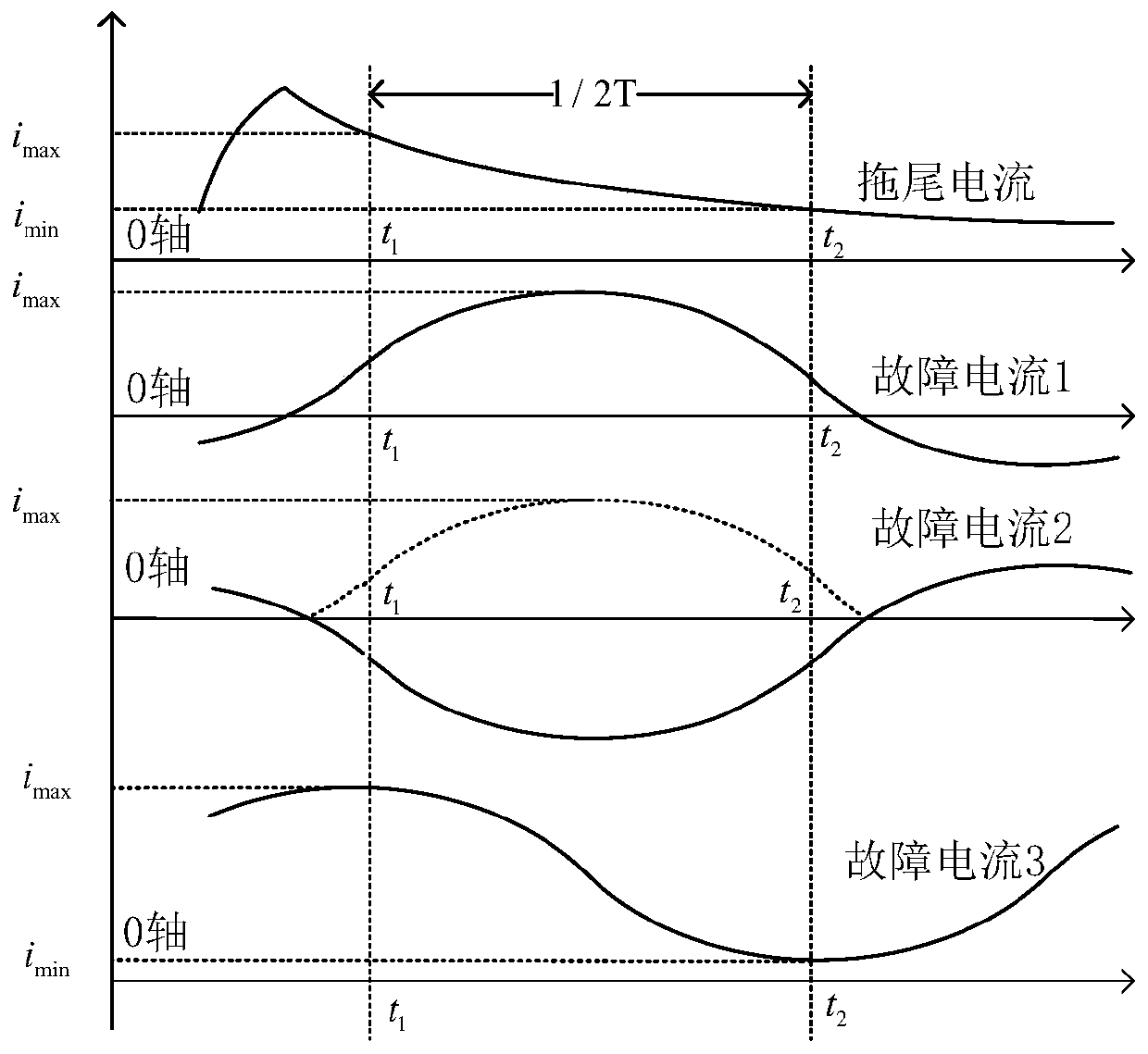
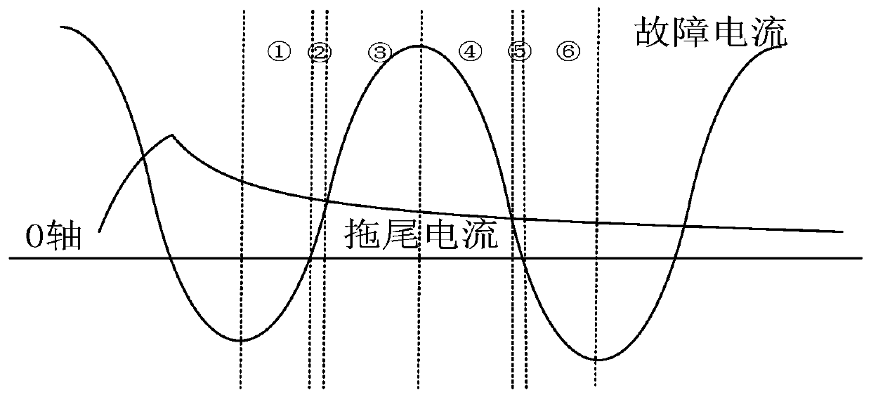
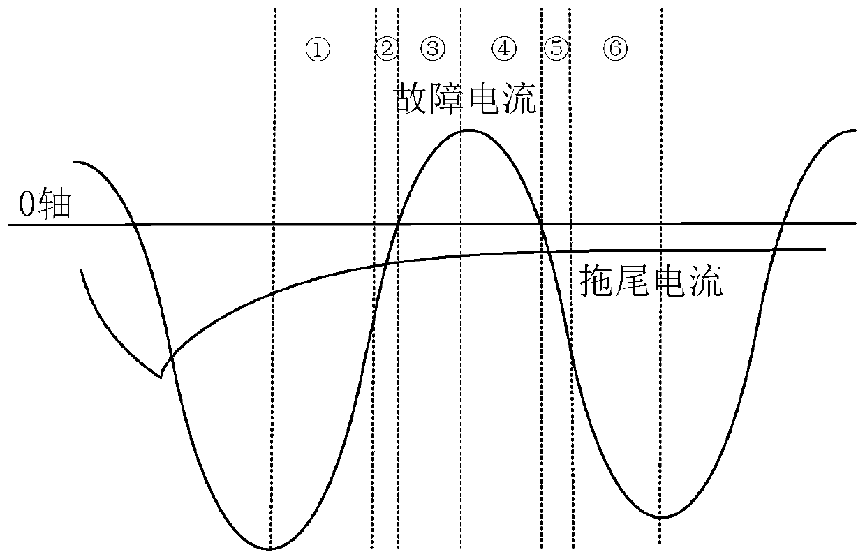
A current transformer trailing current recognition algorithm based on waveform characteristic difference comprises the steps that firstly, the absolute value of the first 1/2 cycle wave of real-time sampling current of a transformer is obtained, the half-wave integral value, the maximum/minimum value and the maximum value deviation in a data window are calculated, and if the maximum value deviation is equal to 0, it is judged that the sampling current meets the maximum value criterion; secondly, every three continuous sampling points is taken as a section, the increase, decrease and convexityof the sampling points of the section are judged, and if the number of the sampling sections which are continuously and progressively decreased and have concave characteristics exceeds a set thresholdvalue, a judgment is made that the sampling current satisfies a subtraction-concavity criterion; further, a comprehsnive judgment is made that data meets the subtraction-concavity criterion, if the half-wave integral value is less than the set threshold, a judgment is made that that the current transformer current is the trailing current. A recognition algorithm is simple in principle, dual in criterion and high in reliability. The method only needs current magnitude information and is easy to implement in engineering.

Description

technical field [0001] The invention relates to a tailing current recognition algorithm of a current transformer based on waveform characteristic difference, which belongs to the field of relay protection of electric power system. Background technique [0002] When a fault occurs in the power system, the relay protection device will send a trip command to the corresponding circuit breaker after confirming the fault, and the circuit breaker will trip the faulty part of the primary side. According to theoretical analysis and on-site verification, due to the presence of inductance components in the current loop of the secondary side of the CT, a small amount of electric energy will be stored in the inductance components. The winding and the secondary load carried by the CT form a loop and release the energy stored in the current loop inductance, so the CT secondary side loop still has an attenuated non-periodic DC component after the circuit breaker disconnects the primary side...

Claims


Application Information

Patent Timeline
Patent Type & Authority Applications(China)
IPC IPC(8): G06K9/00G01R19/175
CPCG01R19/175G06F2218/10Y04S10/52
Inventor 李振兴甘涛张健婷傅裕挺王朋飞王振宇
Owner CHINA THREE GORGES UNIV
Why Eureka
Try Eureka