
Retinoscope capable of being connected with mobile phone to check retinoscopic state

A retinoscopy and mobile phone technology, applied in the field of retinoscopy, can solve the problems of high cost, complex structure, inability to record the detection process, etc., and achieve the effects of reducing production cost, simplifying structure, and facilitating proofreading and inspection results.

Pending Publication Date: 2019-08-16
浏阳市集里医院
View PDF0 Cites 0 Cited by
  • Summary
  • Abstract
  • Description
  • Claims
  • Application Information

AI Technical Summary

Problems solved by technology

[0007] The current retinoscope has its own light source, and the light and shadow of the subject's eyes can be directly observed by medical staff. This method, on the one hand, has a complicated structure and high cost. On the other hand, it cannot record the detection process, and only one person can Viewing, unable to realize multi-person viewing, not suitable for follow-up treatment

Method used


Image

  • Retinoscope capable of being connected with mobile phone to check retinoscopic state
  • Retinoscope capable of being connected with mobile phone to check retinoscopic state
  • Retinoscope capable of being connected with mobile phone to check retinoscopic state

Examples


Embodiment 1

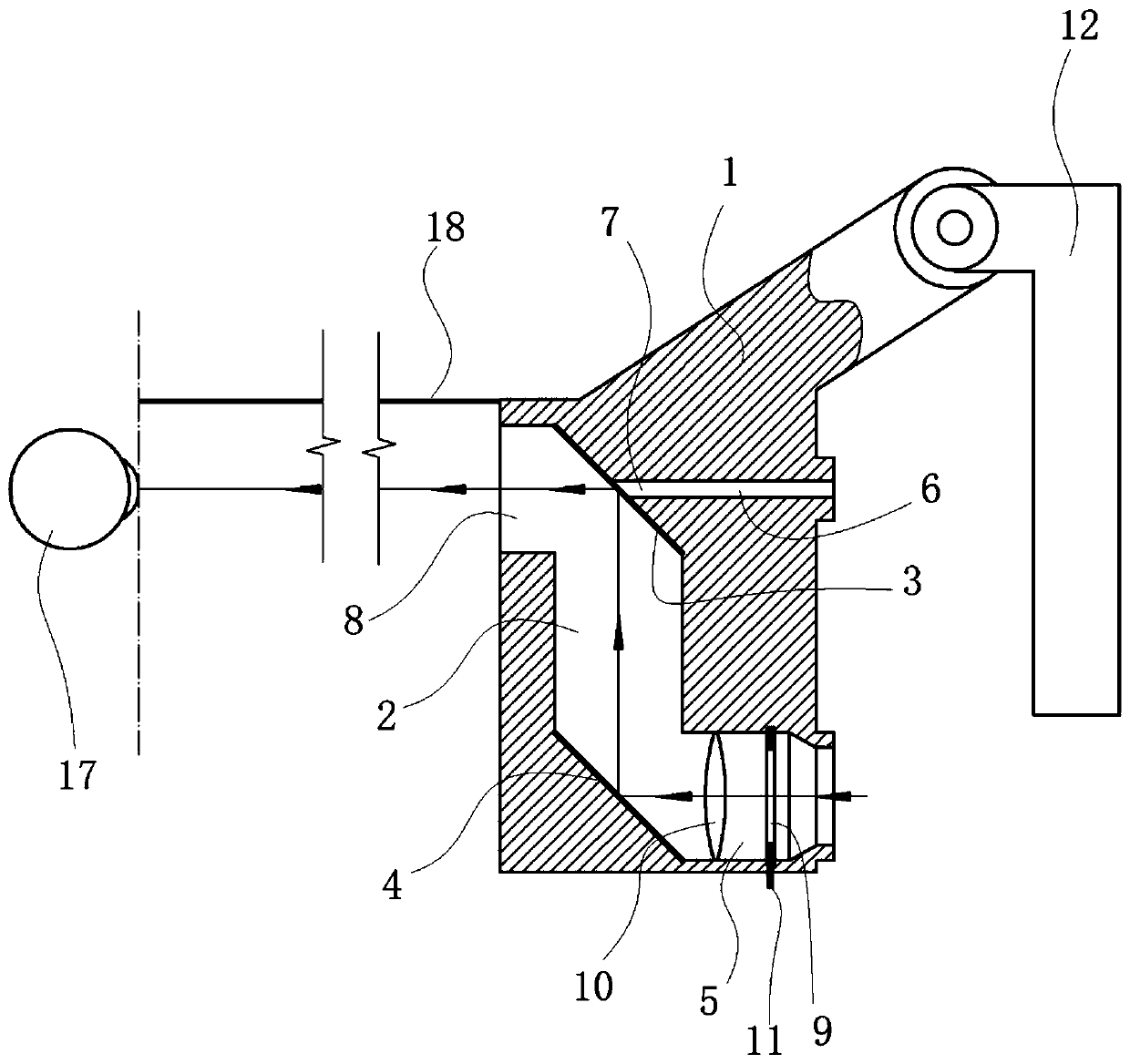
[0034] Such as figure 1 As shown, the embodiment of the present invention includes a body 1 , a reflector A 3 , a reflector B 4 , a light source hole, and a slit plate 9 .

[0035] The body 1 is provided with a reflective cavity, the upper end of the reflective cavity is provided with the reflector armor 3, and the side wall of the reflective cavity positioned at the front side of the reflector armor 3 is provided with an object hole 8, which is located at the reflector armor 3. The side wall of the reflector cavity on the back side of the mirror armor 3 is provided with an eye hole 6, the eye hole 6 is docked with the camera lens of the mobile phone, and the straight line where the object hole 8 and the eye hole 6 are located and the intersection point of the mirror armor 3 are set There are peepholes7.

[0036] The lower end of the reflective cavity is provided with the reflector B 4, and the reflector B 4 is arranged opposite to the mirror surface of the reflector A 3, and...

Embodiment 2

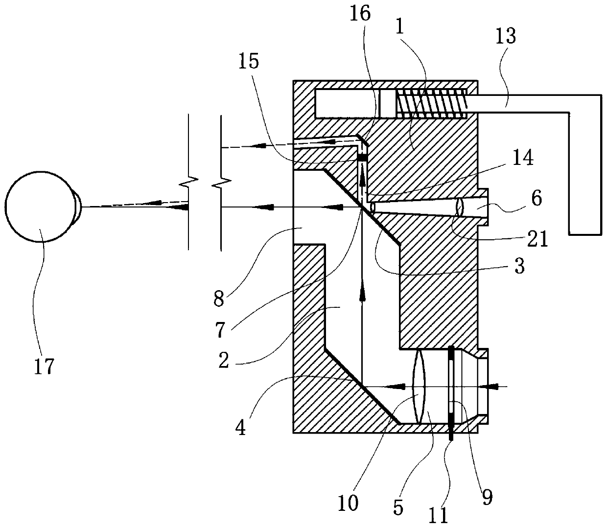
[0045] Such as figure 2 As shown, compared with embodiment 1, embodiment 2 also includes the following technical features:

[0046] The light projected to the peep hole 7 is the distance measuring light, which is the light that is not reflected by the reflector A 3 .

[0047] The extending direction of the distance measuring light is provided with a distance measuring hole 14, that is, the distance measuring hole 14 is located at the back of the reflector A 3 and is on the same straight line as the distance measuring light. The distance measuring hole 14 is provided with a reflector 16 and a colored filter body, and the colored filter body can be used to change the color of the passing light, even if the distance measuring light becomes colored light, the colored filter body adopts red light, so that the measuring The distance from the ray is more pronounced, and it can be faster when finding the convergence point.

[0048] The distance measuring light is reflected to the s...

Embodiment 3

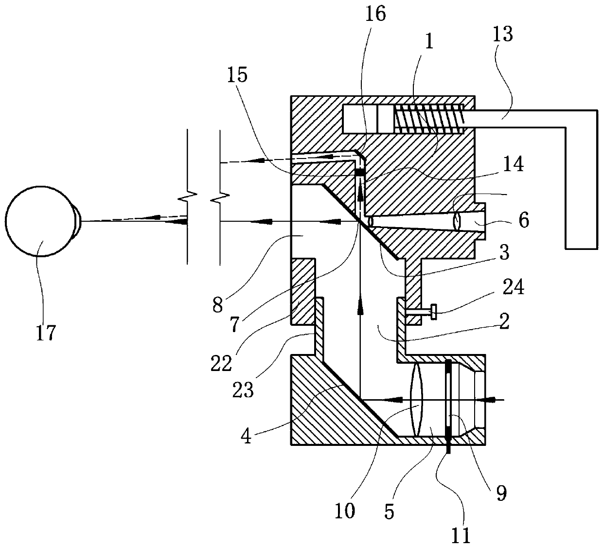
[0053] Such as image 3 As shown, compared with embodiment 2, embodiment 3 also has the following technical features: the reflection cavity 2 includes an upper cylinder 22 and a lower cylinder 23, and the upper end of the lower cylinder 23 is slidably fitted to the lower end of the upper cylinder 22 , the side wall of the upper cylinder 22 is provided with a locking bolt 24 , and the end of the locking bolt 24 abuts against the outer wall of the lower cylinder 23 inwardly. Through the cooperation of the upper barrel and the lower barrel, the distance between the light hole and the eye hole can be adjusted, so as to adapt to the distance between flashlights and lenses of different mobile phones.


PUM


Abstract

The invention belongs to the technical field of retinoscopes and provides a retinoscope capable of being connected with a mobile phone to check retinoscopic state. The retinoscope comprises a body, afirst reflector, a second reflector, a light source hole and a slit plate, the body is provided with a reflection cavity, the first reflector is arranged at the upper end of the reflection cavity, anobject hole is formed in the side wall of the reflection cavity positioned on the front side of the first reflector, an eye hole is formed in the side wall of the reflection cavity positioned on the back side of the first reflector, an orifice of the eye hole is docked with a lens of the mobile phone, and a peephole is formed at an intersection of a straight line on which the object hole and the eye hole are positioned and the first reflector; the second reflector is arranged at the lower end of the reflection cavity and arranged oppositely to a mirror face of the first reflector, a light holeis formed in the side wall of the reflection cavity positioned on the front side of the second reflector, an orifice of the light hole is docked with a flashlight of the mobile phone, and the slit plate is arranged in the light hole. Human eye state under a strip-shaped light belt can be recorded through a lens, multi-person result observation is realized, and production cost can be lowered remarkably.

Description

technical field [0001] The invention relates to the technical field of retinoscopy mirrors, in particular to a retinoscopy mirror that can be connected to a mobile phone to check the status of retinoscopy mirrors. Background technique [0002] The retinoscope is an instrument for measuring the refractive error and astigmatism axis of the human eye. It is equipped with an optical system for filament lighting and imaging. It is used to objectively measure the refractive state of the eyeball. The retinoscope is used to illuminate the inside of the eyeball, and the light is reflected from the retina Come back, these reflected light changes through the diopter of the eyeball, and the refractive state of the eyeball can be judged by checking the change of the reflected light. [0003] Existing retinoscope mainly provides a bundle of strips of light, projects it onto the eyeball, and then slightly swings the retinoscope to make the strips of light move in translation, then you can ...

Claims


Application Information

Patent Timeline
Patent Type & Authority Applications(China)
IPC IPC(8): A61B3/103
CPCA61B3/103
Inventor 杨多李模江邓隐逍赵双喜易湘青黄冬艳王海燕刘辉星梁昊
Owner 浏阳市集里医院
Learn More