Diesel common rail pressure and rotation speed coupling control system based on sliding mode variable structure

A sliding mode variable structure and common rail pressure technology, which is applied in engine control, electrical control, fuel injection control, etc., can solve problems such as lack of reliability, stability and robustness, and unsatisfactory control effects, and achieve the target More optimized performance, good control effect, and guaranteed stability effect

Inactive Publication Date: 2019-08-16
WUHAN UNIV OF TECH
View PDF0 Cites 3 Cited by
  • Summary
  • Abstract
  • Description
  • Claims
  • Application Information

AI Technical Summary

Problems solved by technology

Most of the control systems of diesel engines at home and abroad use the fuzzy-PID control method to control parameters such as temperature, pressure and speed, but the control effect of some parameters and systems is not very ideal, and the reliability, stability and robustness are all poor. There are deficiencies

Method used


Image

  • Diesel common rail pressure and rotation speed coupling control system based on sliding mode variable structure
  • Diesel common rail pressure and rotation speed coupling control system based on sliding mode variable structure
  • Diesel common rail pressure and rotation speed coupling control system based on sliding mode variable structure

Examples


Embodiment Construction

[0023] The present invention will be further described below in conjunction with the accompanying drawings and embodiments.

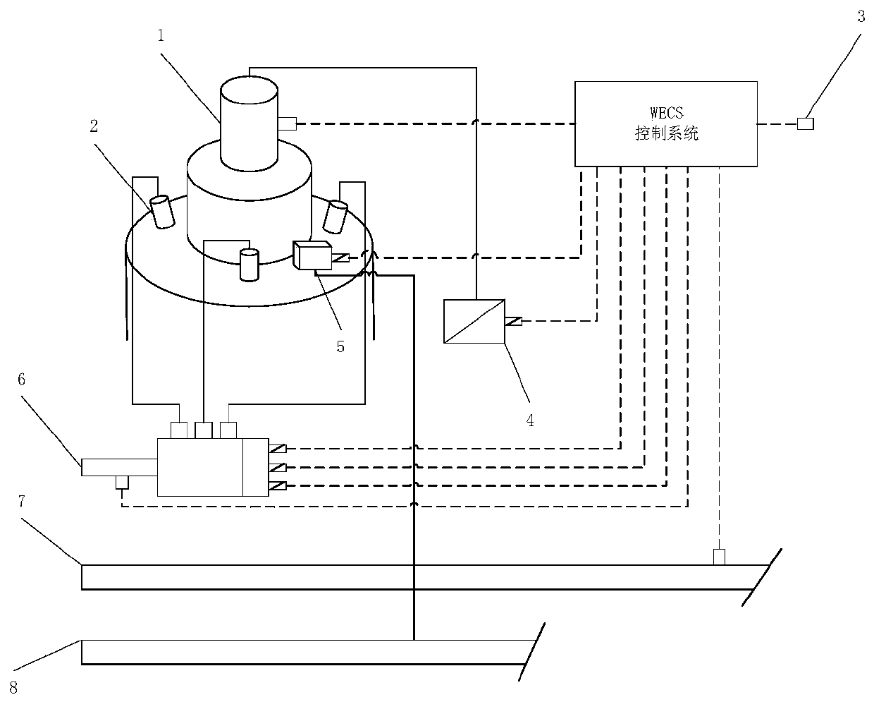
[0024] A diesel engine common rail pressure and speed coupling control system based on sliding mode variable structure, such as figure 1 As shown, it includes a fuel injector 2, a fuel injection control unit 6 for controlling the fuel injection quantity of the fuel injector 2, a high-pressure common rail pipe 7 for supplying fuel to each fuel injector 2, a speed sensor 3 for detecting the speed of the diesel engine, and a control valve ( Not shown in the figure), the fuel in the high-pressure common rail pipe 7 is delivered by the crankshaft through the gear transmission to drive the high-pressure oil pump (the high-pressure oil pump generally adopts a plunger type), and the common rail pressure in the high-pressure common rail pipe 7 is set by the engine control system and The fuel injection control unit 6 includes a piston flow switch, and the control...


PUM


Abstract

The invention discloses a diesel common rail pressure and rotation speed coupling control system based on a sliding mode variable structure. The diesel common rail pressure and rotation speed couplingcontrol system based on the sliding mode variable structure comprises a fuel injector, a fuel injector control unit, a high pressure common rail tube, a rotation speed sensor and a control valve, wherein common rail pressure in the high pressure common rail tube is set and controlled by an engine control system, and adjusted along with changes of engine load, the control valve comprises an electromagnetic valve located on a fuel inlet pipeline of the high pressure common rail tube and used for changing the capacity of a hydraulic cavity, a counterbalance valve located on a fuel return pipeline of the high pressure common rail tube, a pilot-operated type overpressure regulating valve located on the upper stream of the high pressure common rail tube and used for overpressure protection, anda pilot valve which controls fuel injection quantity by changing pressure of front and rear cavities of a piston in a piston type flow switch, a non-linear relationship between the rotation speed andthe fuel injection quantity of a diesel is represented through a non-linear speed regulating system model based on the sliding mode variable structure, and stability of fuel injection is guaranteed by using the non-linear speed regulating system model and controlling the control valve. The diesel common rail pressure and rotation speed coupling control system based on the sliding mode variable structure guarantees stability of the fuel injection, and is good in reliability, stability and robustness.

Description

technical field [0001] The invention belongs to the field of marine diesel engines, and in particular relates to a diesel engine common rail pressure and rotational speed coupling control system based on sliding mode variable structure. Background technique [0002] Diesel engines have been widely used in industry, agriculture, national defense and other fields, and extensive research has been carried out on the transformation of diesel engine full electronic control. Since the 1990s, countries around the world have taken diesel engine electronic control technology as one of the indicators to measure the advanced nature of diesel engines. . Energy shortage, environmental protection issues, development of microelectronics technology and control theory, and improvement of automation requirements have promoted the development of diesel engine electronic control technology, especially digital electronic control technology innovation with computer as the core, centered on electro...

Claims


Application Information

Patent Timeline
Patent Type & Authority Applications(China)
IPC IPC(8): F02D41/38F02D31/00
CPCF02D31/00F02D41/3827F02D41/3836F02D41/3845
Inventor 毛小兵马哲轩蔡乐岳健鹏
Owner WUHAN UNIV OF TECH
Why Eureka
Try Eureka