Valve body of automobile hydraulic brake valve and production process thereof

A hydraulic brake valve and valve body technology, applied in the field of auto parts, can solve the problems of many variable factors, losses, and more serious piston wear, and achieve the effects of high structural strength, long service life, and stable oil pressure

Pending Publication Date: 2019-01-01
大昌汽车部件(苏州)有限公司
View PDF0 Cites 2 Cited by
  • Summary
  • Abstract
  • Description
  • Claims
  • Application Information

AI Technical Summary

Problems solved by technology

When the piston moves back and forth in the valve body, it is easy to cause wear and tear. Although the existing valve body can meet the needs of hydraulic braking, the structure of the valve body is not optimized enough, and the size relationship between the valve cavity, the oil inlet hole and the oil outlet hole is unreasonable. , so that the wear of the piston is more serious, and the hydraulic oil is likely to cause losses when transmitting power; under ordinary braking, the temperature in the valve body will rise, resulting in an increase in pressure. On the one hand, it can dissipate heat, and on the other hand, it can improve the structural strength of the valve body, but this solution will increase the volume of the valve body, increasing the difficulty and cost of production
[0003] In terms of production, the design of the production process is also particularly important, because during the machining process, the internal temperature of the workpiece will rise, which will easily cause deformation. If it is not handled properly, it will directly affect the quality of the workpiece, especially the oxidation treatment. There are many variable factors and improper control, and the ideal oxide layer cannot be formed

Method used


Image

  • Valve body of automobile hydraulic brake valve and production process thereof
  • Valve body of automobile hydraulic brake valve and production process thereof
  • Valve body of automobile hydraulic brake valve and production process thereof

Examples


Embodiment Construction

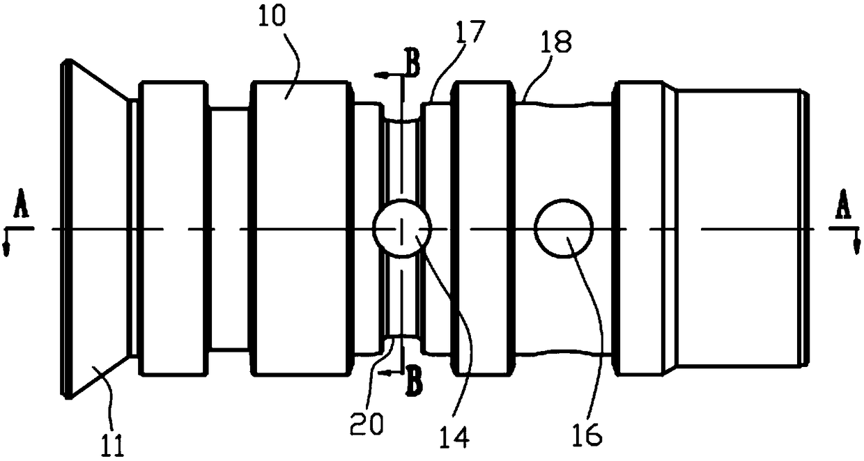
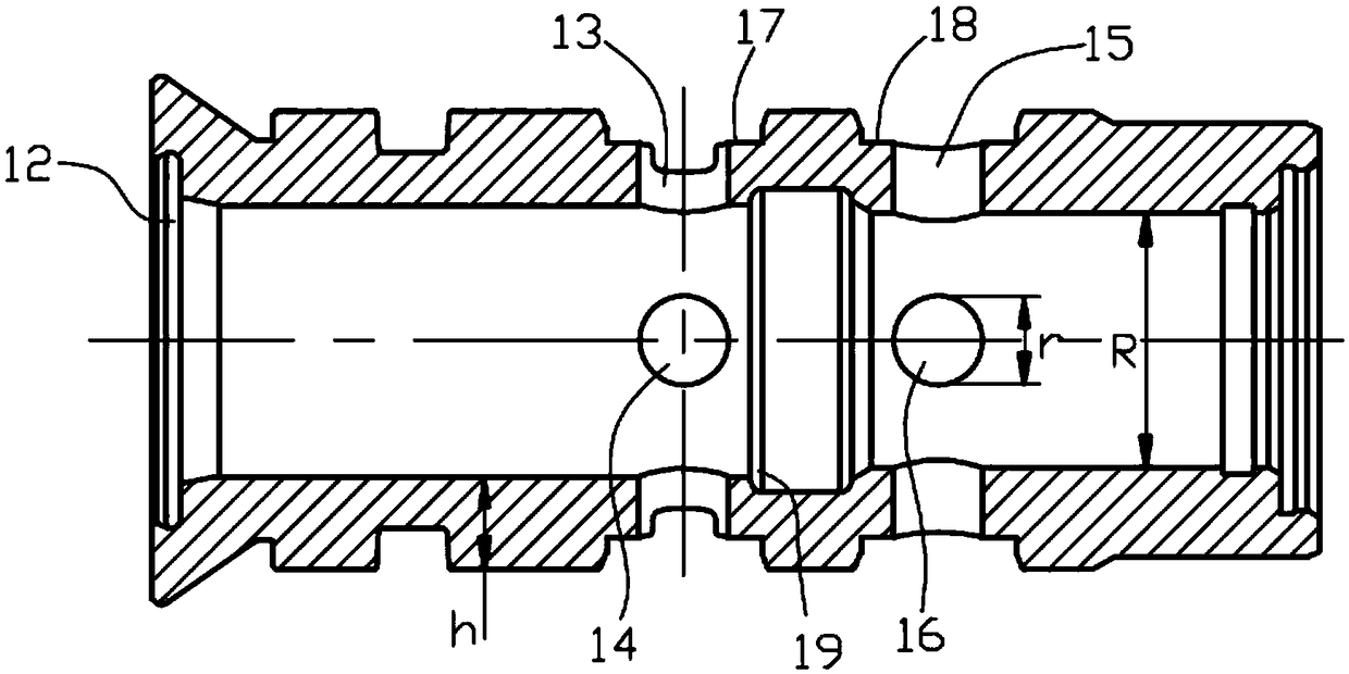
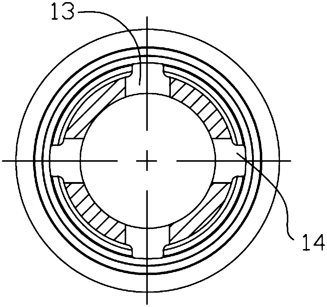
[0024] Below in conjunction with accompanying drawing, the present invention will be further described with specific embodiment, see figure 1 —3: A valve body of an automobile hydraulic brake valve, the valve body 10 includes two connected ports, and the inner walls of the two ports are provided with connecting threads 12, wherein one port of the valve body 10 is set as The tapered end surface 11 is convenient to further fix the valve body 10 and prevent the port from falling off. The middle part of the valve body 10 is provided with four groups of radial through holes, which are radial through holes I13, radial through holes II14, radial through holes Hole III15 and radial through hole IV16, said radial through hole I13 and radial through hole II14 are perpendicular to and intersect each other, said radial through hole III15 and radial through hole IV16 are mutually perpendicular and intersecting, said valve body 10 There is an annular groove I19 inside. The annular groove I1...


PUM

PropertyMeasurementUnit
thicknessaaaaaaaaaa
hardnessaaaaaaaaaa
hardnessaaaaaaaaaa

Abstract

The invention particularly relates to a valve body of an automobile hydraulic brake valve and a production process thereof, belonging to the technical field of automobile spare parts, the valve body includes two communicating ports, a conical end face is arranged at one of the ports of the valve body, four sets of radial through holes are arranged in the middle of the valve body, which are a radial through hole I, a radial through hole II, a radial through hole III and a radial through hole IV, the radial through hole I and the radial through hole II are perpendicular to and intersect with each other, the radial through hole III and the radial through hole IV are perpendicular to and intersect with each other, the wall thickness of the valve body is h, the inner diameter of the valve bodyis R, the radial through hole I, the radial through hole II, the radial through hole III and the radial through hole IV have the same aperture r, and r<h<2r<R<3r. The valve body has the advantages ofsimple structure, light weight, high structural strength, long service life, and can provide stable oil pressure, so that the braking is faster and more sensitive.

Description

technical field [0001] The invention belongs to the technical field of automobile spare parts, and relates to a brake valve, in particular to a valve body of an automobile hydraulic brake valve and a production process thereof. Background technique [0002] Automobile braking adopts hydraulic control, which can obtain more stable braking force, and has quick response, sensitivity and labor saving. When the piston moves back and forth in the valve body, it is easy to cause wear and tear. Although the existing valve body can meet the needs of hydraulic braking, the structure of the valve body is not optimized enough, and the size relationship between the valve cavity, the oil inlet hole and the oil outlet hole is unreasonable. , so that the wear of the piston is more serious, and the hydraulic oil is likely to cause losses when transmitting power; under ordinary braking, the temperature in the valve body will rise, resulting in an increase in pressure. On the one hand, it can...

Claims


Application Information

Patent Timeline
Patent Type & Authority Applications(China)
IPC IPC(8): B60T11/28B23P15/00
CPCB60T11/28B23P15/001
Inventor 潘松辉潘菁李刚
Owner 大昌汽车部件(苏州)有限公司
Why Eureka
Try Eureka