
A submarine power generation device using tides

A power generation device and tidal technology, which is applied to ocean energy power generation, hydropower generation, reaction engines, etc., can solve problems such as inability to generate electricity, blades cannot rotate, and influence on the marine ecological environment, and achieve the effect of convenient use and long service life

Active Publication Date: 2020-11-24
ANHUI KANGYU HYDROPOWER MACHINERY COMPLETE EQUIP CO LTD
View PDF6 Cites 0 Cited by
  • Summary
  • Abstract
  • Description
  • Claims
  • Application Information

AI Technical Summary

Problems solved by technology

[0002] A generator refers to a mechanical device that converts other forms of energy into electrical energy. It is driven by a water turbine, steam turbine, diesel engine or other power machinery, and converts the energy generated by water flow, air flow, fuel combustion or nuclear fission into mechanical energy and transmits it to the generator. A device that converts the generator into electrical energy. At present, there are also tidal generators that use the ebb and flow of seawater to generate electricity. The tidal generator uses the tide to drive the blades, thereby driving the internal motor to convert tidal energy into electrical energy. The tidal generator blades The rotation will stir up the seawater and hang the organisms in the seawater, thereby affecting the ecological environment of the ocean, and the blades of the tidal generator are easily entangled by impurities such as seaweed, so that the blades of the tidal generator cannot rotate and thus cannot generate electricity, and This kind of tidal generator is extremely difficult to install and other problems

Method used


Image

  • A submarine power generation device using tides
  • A submarine power generation device using tides
  • A submarine power generation device using tides

Examples


Embodiment Construction

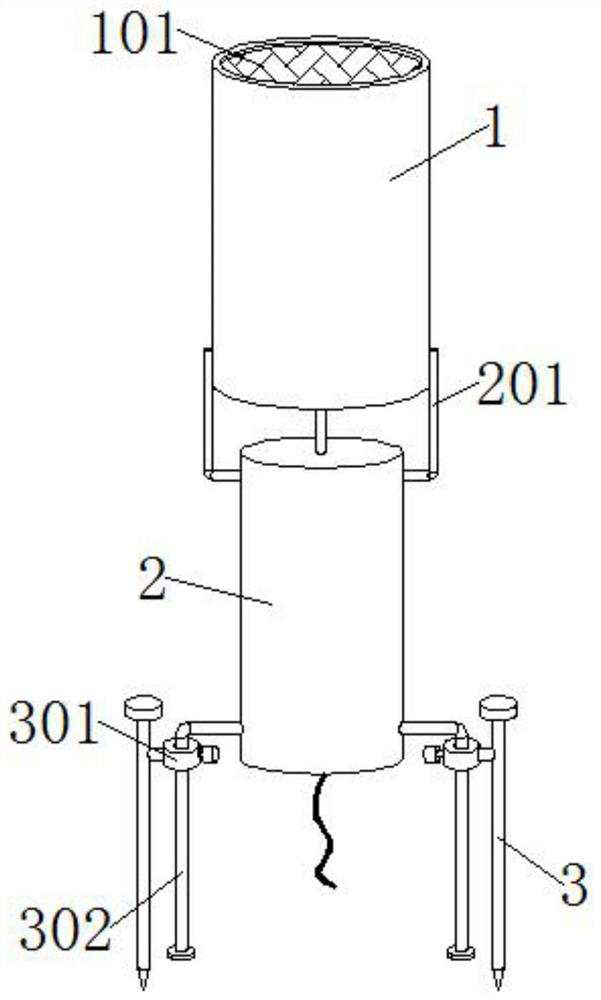
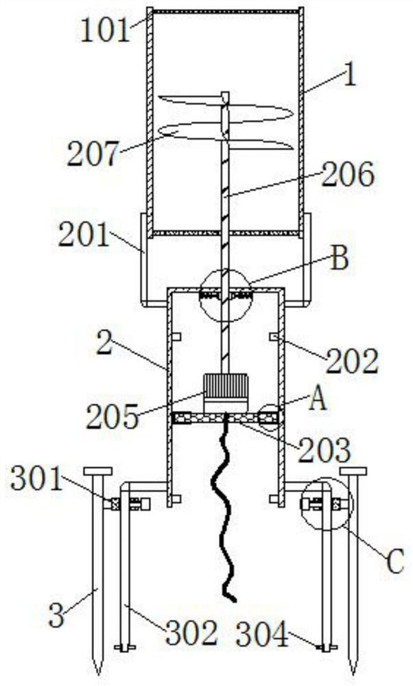
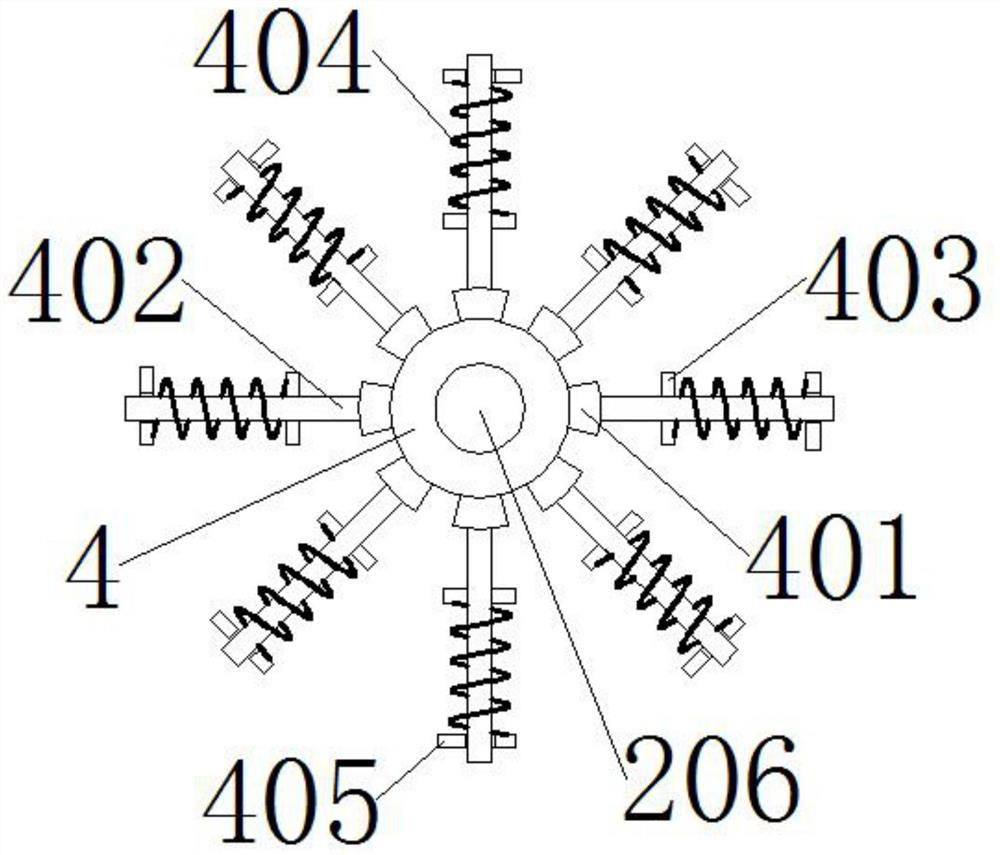
[0025] see Figures 1 to 6 Among them, in the embodiment of the present invention, a submarine power generation device using tides includes a protection cylinder 1, a sealing ring 4, a fixed rod 3 and a vacuum cylinder 2. The bottom of the protection cylinder 1 is welded with a vacuum cylinder 2, and the bottom of the vacuum cylinder 2 is Both sides of the protective tube 1 are welded with fixed rods 3, the top of the inner wall of the vacuum cylinder 2 is tightly fitted with a sealing ring 4, and the inner wall of the protective cylinder 1 is welded with two mesh sieve plates 101; the vacuum cylinder 2 includes a support rod 201, a collar 202, piston plate 203, rubber sleeve 204, generator 205, rotating shaft 206 and helical blade 207, both sides of the vacuum cylinder 2 top are welded with support rods 201, and the support rods 201 are respectively welded on the two sides of the protection cylinder 1 bottom. On the other hand, the inner wall of the vacuum cylinder 2 is welde...


PUM


Abstract

The invention provides a seabed power generation device using tide. The seabed power generation device comprises a protection cylinder, a sealing ring, fixed rods and a vacuum cylinder, wherein the vacuum cylinder is welded on the bottom of the protection cylinder; the fixed rods are welded on two sides of the bottom of the vacuum cylinder; the sealing ring is tightly attached on the top of the inner wall of the vacuum cylinder; two mesh sieve plates are welded on the inner wall of the protection cylinder; support rods are respectively welded on two sides of the top of the vacuum cylinder; andthe support rods are respectively welded on two sides of the bottom of the protection cylinder. According to the seabed power generation device using tide, the protection cylinder and the mesh sieveplates are capable of preventing marine organisms from being close to a helical blade in the power generation process; the influence on the marine environment can be avoided; the rotation of the helical blade is not easily influenced; the power can be continuously generated; meanwhile, a power generator is mounted at the bottom of a neritic region and is not impacted by sea wave and scoured by rainstorm; and the seabed power generation device has the advantages of long service life and convenience in usage.

Description

technical field [0001] The invention relates to the technical field of generators, in particular to a seabed power generation device utilizing tides. Background technique [0002] A generator refers to a mechanical device that converts other forms of energy into electrical energy. It is driven by a water turbine, steam turbine, diesel engine or other power machinery, and converts the energy generated by water flow, air flow, fuel combustion or nuclear fission into mechanical energy and transmits it to the generator. A device that converts the generator into electrical energy. At present, there are also tidal generators that use the ebb and flow of seawater to generate electricity. The tidal generator uses the tide to drive the blades, thereby driving the internal motor to convert tidal energy into electrical energy. The tidal generator blades The rotation will stir up the seawater and hang the organisms in the seawater, thereby affecting the ecological environment of the oce...

Claims


Application Information

Patent Timeline
Patent Type & Authority Patents(China)
IPC IPC(8): F03B13/26F03B11/00F03B11/08F03B3/12
CPCF03B3/121F03B11/00F03B11/08F03B13/26F05B2240/9151Y02E10/20Y02E10/30
Inventor 张国辉
Owner ANHUI KANGYU HYDROPOWER MACHINERY COMPLETE EQUIP CO LTD
Learn More