
Rapid spherical coordinate laser radar simulation method

A technology of lidar and simulation method, applied in the field of simulation

Active Publication Date: 2019-08-16
北京奥特贝睿科技有限公司
View PDF6 Cites 8 Cited by
  • Summary
  • Abstract
  • Description
  • Claims
  • Application Information

AI Technical Summary

Problems solved by technology

[0006] In view of this, the present invention proposes a fast simulation method for lidar, which still uses the traditional rendering pipeline, is compatible with most types of graphics cards, and can obtain the acceleration performance of modern graphics cards, while solving the problem of equidistant sampling in lidar simulation. The problem of realizing high-speed and high-precision equiangular sampling

Method used


Image

  • Rapid spherical coordinate laser radar simulation method
  • Rapid spherical coordinate laser radar simulation method
  • Rapid spherical coordinate laser radar simulation method

Examples


Embodiment Construction

[0118] It should be noted that the embodiments of the present invention and the features in the embodiments can be combined with each other if there is no conflict.

[0119] The technical solution of the present invention will be further described in detail below in conjunction with the accompanying drawings:

[0120] The present invention requires the CPU and GPU to perform cooperative operations.

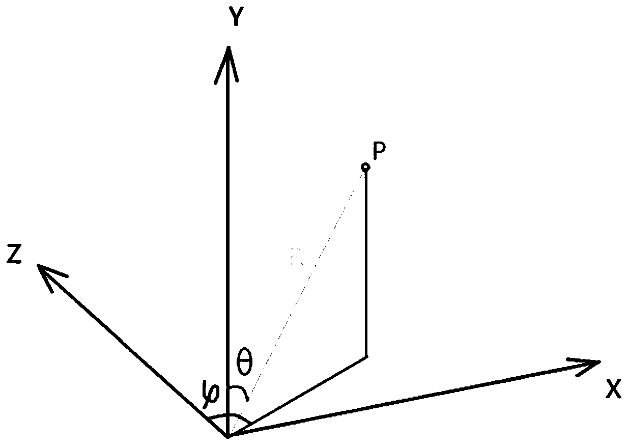
[0121] In the present invention, the rectangular coordinate system is defined as a left-handed coordinate system. That is, the front direction of the object is the Z axis, the right side is the X axis, and the upper side is the Y axis.

[0122] Define the spherical coordinate system as:

[0123] ψ is the angle between the projection of a point P on the XZ plane and the Z axis in space.

[0124] θ is the angle between a point P and the Y axis in space.

[0125] R is the distance of a point P from the origin in space.

[0126] Defined as figure 2 Shown.

[0127] The CPU needs to perform some in...


PUM


Abstract

The invention relates to a rapid spherical coordinate laser radar simulation method, and discloses a rapid simulation method for a laser radar. A CPU and a GPU perform collaborative operation; the CPUperforms partial initialization operation; the GPU performs coordinate conversion on vertex coordinates of triangular surfaces in a vertex shader; in a geometric shader, each triangular surface is changed into a rectangle composed of two triangles, and the coordinates of three vertexes ABC of the original triangular surface are mounted and output; and in a fragment shader, ray detection is performed on the triangular surface, collision point coordinates are calculated, and an output of the laser radar is calculated and mapped to a space (R, G, B, A). According to the method, traditional render pipelines are used, most types of display cards are compatible, and the acceleration performance of the modern display card can be obtained; and meanwhile, the problem of equidistant sampling in laser radar simulation is solved, and the high-speed and high-precision equiangular sampling is realized.

Description

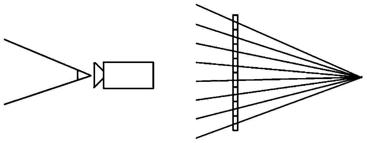
Technical field [0001] The invention belongs to the field of simulation technology, and particularly relates to a fast spherical coordinate lidar simulation method. Background technique [0002] Currently, lidar is widely used in fields such as autonomous driving, robotics, ships, and aviation. However, in the current mainstream simulation system, the simulation of lidar is still at the stage of using a depth camera or using a CPU to calculate Raycast (ray detection). [0003] For example, in Microsoft's AirSim simulation system and LG's LG Simulator simulation system, depth cameras are used as lidar simulation methods. [0004] This kind of simulation has a serious problem: when the virtual camera is sampling, it is sampling equidistantly according to the screen pixels, such as figure 1 As shown, the beam of the camera is actually emitted from the origin, and the direction is from the origin of the camera to the position of each pixel on the NearClip. Therefore, the traditional ren...

Claims


Application Information

Patent Timeline
IPC IPC(8): G01S7/497
CPCG01S7/497
Inventor 居阳
Owner 北京奥特贝睿科技有限公司
Learn More