Test system suitable for air-cooled hydrogen fuel cell

A fuel cell and test system technology, applied in the direction of fuel cells, circuits, electrical components, etc., can solve the problems of low modularity and inability to connect hydrogen fuel cell test platforms

Pending Publication Date: 2019-08-16
向得夫
View PDF2 Cites 18 Cited by
  • Summary
  • Abstract
  • Description
  • Claims
  • Application Information

AI Technical Summary

Problems solved by technology

[0005] Existing technologies mainly focus on testing the performance of water-cooled hydrogen fuel cell systems, and rarely involve research on air-cooled hydrogen fuel cells. Moreover, the existing hydrogen fuel cell test platforms are not highly modular and cannot be well integrated with other Test system for easy connection

Method used


Image

  • Test system suitable for air-cooled hydrogen fuel cell
  • Test system suitable for air-cooled hydrogen fuel cell

Examples


Embodiment 1

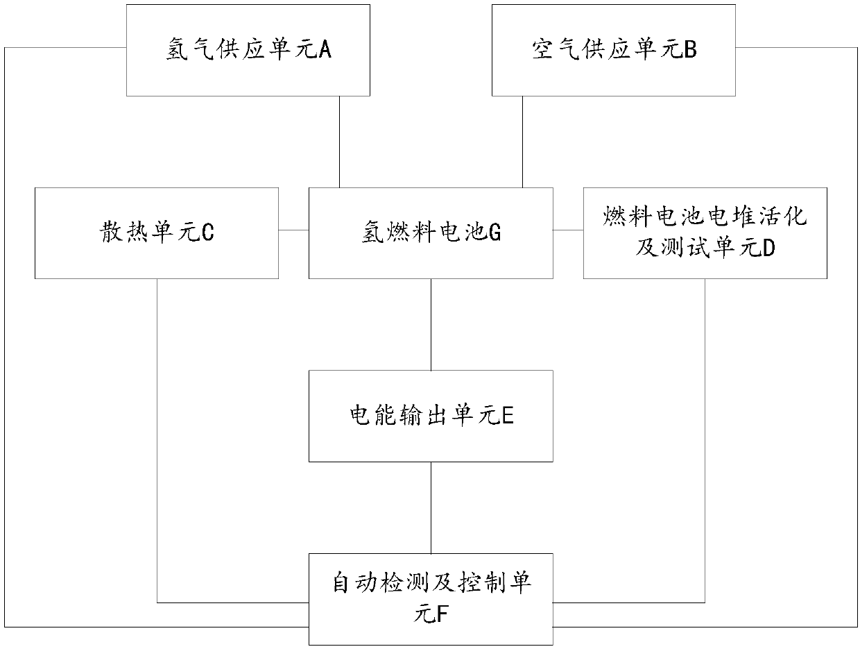
[0045] see figure 1 , the present invention discloses a test system suitable for air-cooled hydrogen fuel cells. The test system includes: hydrogen supply unit A, air supply unit B, heat dissipation unit C, fuel cell stack activation and test unit D, electric energy Output unit E, automatic detection and control unit F.

[0046] The hydrogen supply unit A and the air supply unit B are respectively connected to the fuel cell stack of the hydrogen fuel cell G; the hydrogen supply unit A supplies hydrogen to the fuel cell stack, and the air supply unit B supplies oxygen-containing gas to the fuel cell stack. Air.

[0047] The heat dissipation unit C is arranged close to the fuel cell stack, and uses a fan to dissipate heat from the fuel cell stack.

[0048] The fuel cell stack activation and testing unit D is connected to the fuel cell stack for activation and various performance tests of the fuel cell stack.

[0049] The electric energy output unit E includes a power supply m...

Embodiment 2

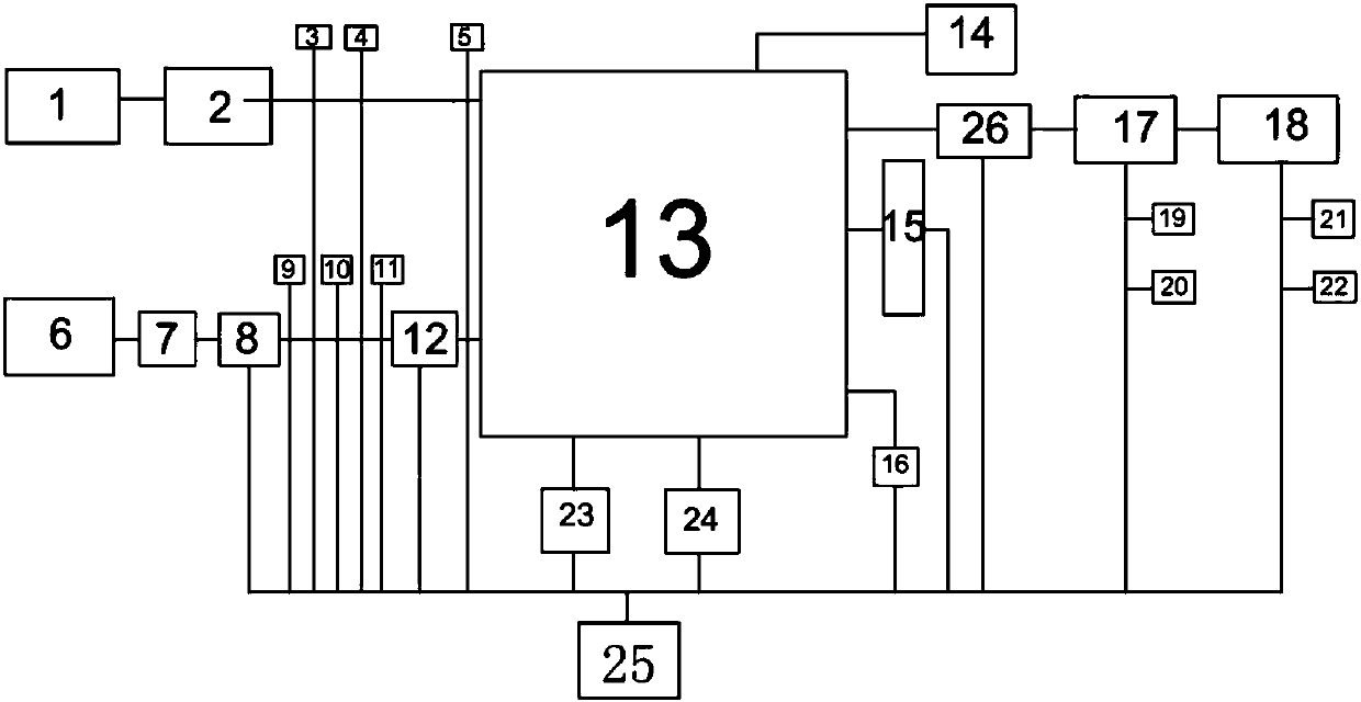
[0061] The present invention discloses a test system suitable for air-cooled hydrogen fuel cells. The test system includes: a hydrogen supply unit A, an air supply unit B, a heat dissipation unit C, an electric energy output unit E, and an automatic detection and control unit F.

[0062] The hydrogen supply unit A and the air supply unit B are respectively connected to the fuel cell stack of the hydrogen fuel cell G; the hydrogen supply unit A supplies hydrogen to the fuel cell stack, and the air supply unit B supplies oxygen-containing gas to the fuel cell stack. Air.

[0063] The heat dissipation unit C is arranged close to the fuel cell stack, and uses a fan to dissipate heat from the fuel cell stack.

[0064] The electric energy output unit E includes a power supply module and an electronic load, and is responsible for outputting electricity produced by the fuel cell stack.

[0065] The automatic detection and control unit F includes an upper computer and a sensor group, ...


PUM


Abstract

The invention discloses a test system suitable for air-cooled hydrogen fuel cell. The system comprises a hydrogen supply unit, an air supply unit, a heat dissipation unit, an electric energy output unit and an automatic detection and control unit; the hydrogen supply unit and the air supply unit are connected with the fuel cell stack of the hydrogen fuel cell; the hydrogen supply unit supplies hydrogen to the fuel cell stack, and the air supply unit supplies air to the fuel cell stack; the heat dissipation unit is arranged close to the fuel cell stack, and employs a fan to perform heat dissipation for the fuel cell stack; the electric energy output unit comprises a power module and an electronic load and is configured to output electricity generated by the fuel cell stack; the automatic detection and control unit comprises an upper computer and a sensor set, the upper computer performs detection and control for the set parameters in the test system. The test system suitable for air-cooled hydrogen fuel cell can test the running conditions of the air-cooled hydrogen fuel cell power generation system under different test conditions, so that the optimal running condition is obtained.

Description

technical field [0001] The invention belongs to the technical field of new energy and relates to a hydrogen fuel cell, in particular to a test system suitable for an air-cooled hydrogen fuel cell. Background technique [0002] Hydrogen fuel cells generally use hydrogen or reformed hydrogen as fuel, and air or oxygen as oxidant to convert chemical energy into electrical energy. Hydrogen fuel cells are divided into air-cooled type and water-cooled type according to the heat dissipation method. The flow rate, temperature and humidity of hydrogen, the flow rate, temperature and humidity of air, as well as the temperature and other physical parameters of the fuel cell stack itself have an important impact on the normal operation and power generation efficiency of the fuel cell. [0003] Patent 201610152403.7 provides a test platform for testing the water-cooled fuel cell hydrogen system, which can simulate the state of the hydrogen system when the fuel cell system is running, so...

Claims


Application Information

Patent Timeline
Patent Type & Authority Applications(China)
IPC IPC(8): H01M8/04313
CPCH01M8/04313Y02E60/50
Inventor 向得夫
Owner 向得夫
Why Eureka
Try Eureka