
Wireless power supply system circuit topology applied to rail transit

A wireless power supply, rail transit technology, applied in circuit devices, electrical components, etc., to achieve the effect of reducing operating current, reducing system loss, and reducing output current ripple

Inactive Publication Date: 2019-08-16
TSINGHUA UNIV
View PDF6 Cites 6 Cited by
  • Summary
  • Abstract
  • Description
  • Claims
  • Application Information

AI Technical Summary

Problems solved by technology

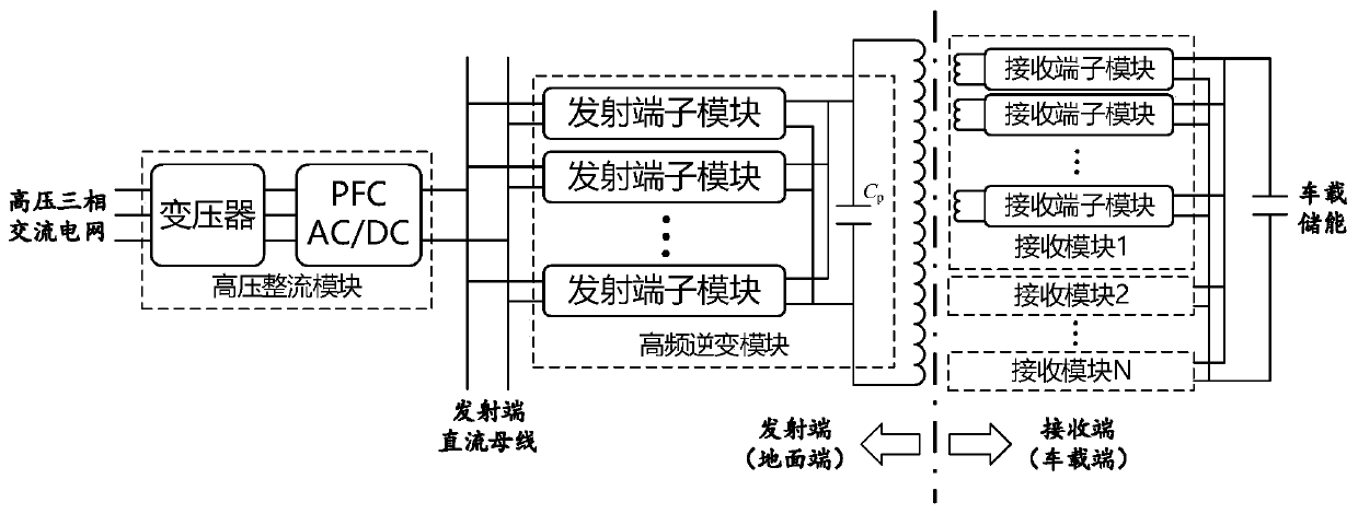
[0005] In view of the above problems, the present invention proposes a circuit topology of a wireless power supply system applied to rail transit. Through the modular combination of a high-frequency converter and a resonant topology, the difficulty of realizing a single sub-module in a high-power wireless power supply system is reduced, and it solves the problem of The circulation problem of sub-module parallel connection and the matching problem between parallel structure and resonant network are solved. At the same time, according to the characteristics of rail transit applications, the proposed circuit topology can meet the requirements of one-to-many and mobile wireless power supply.

Method used


Image

  • Wireless power supply system circuit topology applied to rail transit
  • Wireless power supply system circuit topology applied to rail transit
  • Wireless power supply system circuit topology applied to rail transit

Examples


Embodiment Construction

[0021] In order to make the objectives, technical solutions and advantages of the present invention clearer, the technical solutions in the embodiments of the present invention will be described in more detail below in conjunction with the drawings in the embodiments of the present invention. In the drawings, the same or similar reference numerals denote the same or similar elements or elements having the same or similar functions throughout. The described embodiments are some, but not all, embodiments of the invention. The embodiments described below by referring to the figures are exemplary and are intended to explain the present invention and should not be construed as limiting the present invention. Based on the embodiments of the present invention, all other embodiments obtained by persons of ordinary skill in the art without creative efforts fall within the protection scope of the present invention.

[0022] Such as figure 1 As shown, the schematic diagram of the overa...


PUM


Abstract

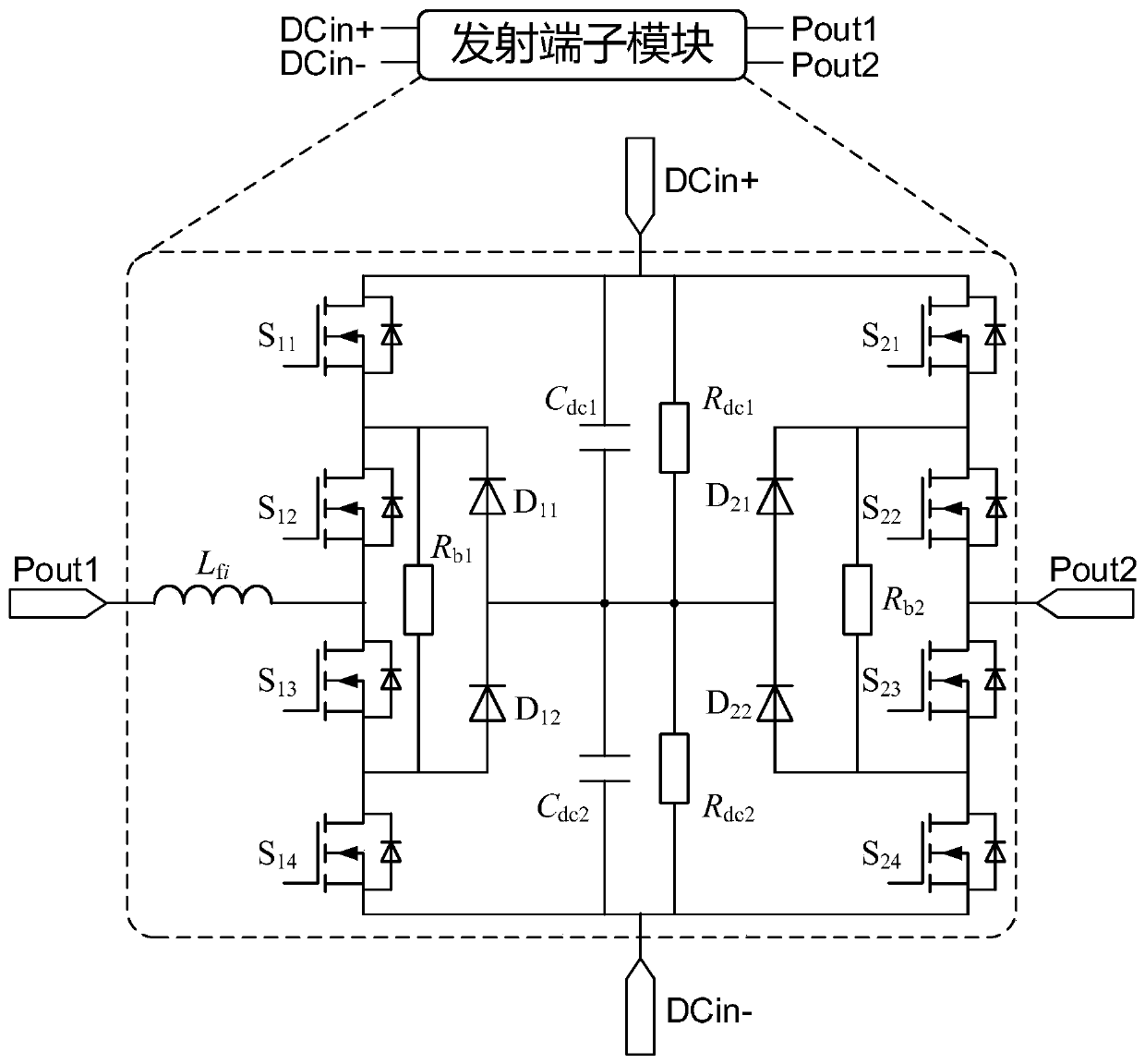
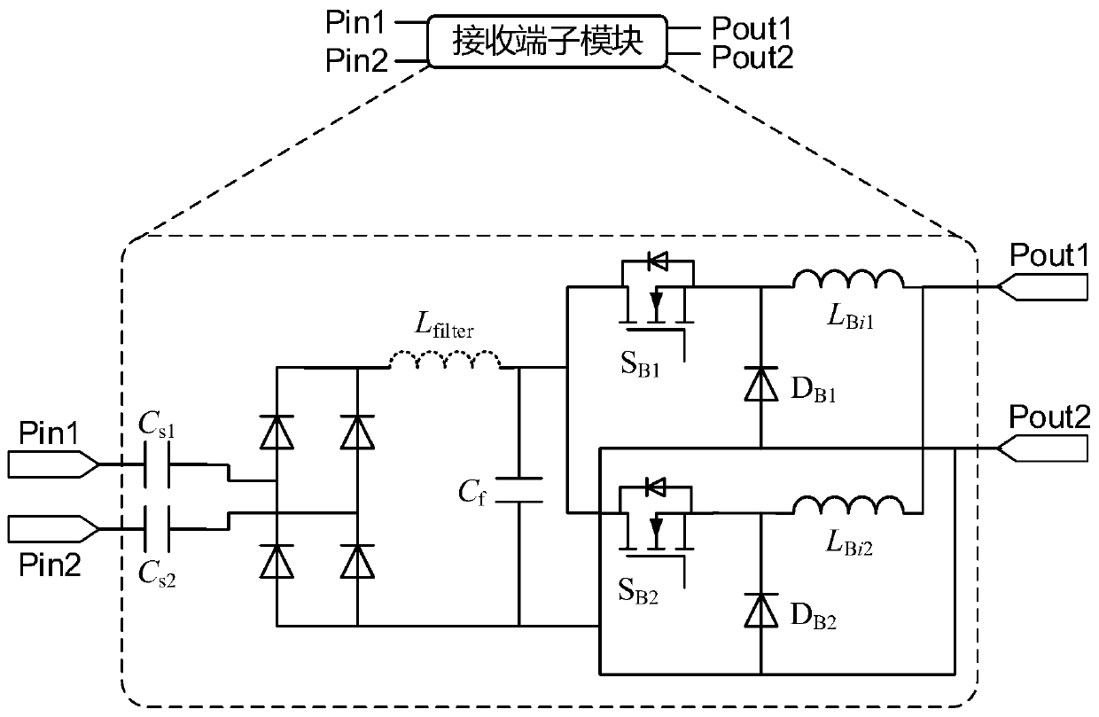
The invention discloses a wireless power supply system circuit topology applied to rail transit, which includes a high-voltage rectifier module, a transmitter DC bus, a high-frequency inverter module,a magnetically coupled transmitting mechanism and receiving modules. The input end of the high-voltage rectifier module is a high-voltage three-phase AC grid, and the output end is connected with thehigh-frequency inverter module through the transmitter DC bus. The high-frequency inverter module includes a plurality of transmitting terminal modules and a primary resonant capacitor Cp, which areconnected with the magnetically coupled transmitting mechanism after parallel output. Each receiving module is composed of a plurality of receiving terminal modules and the same number of magneticallycoupled receiving mechanisms. The receiving terminal modules of the same receiving module supply power to a vehicle energy storage system after interleaved parallel output.

Description

technical field [0001] The invention relates to the technical field of power electronics, in particular to a circuit topology of a wireless power supply system applied to rail transit. Background technique [0002] Rail transit includes various forms such as high-speed rail, subway, light rail, tram, and maglev train. Most of its power supply methods currently use contact power supply, such as overhead lines and pantograph power supply, or third-rail power supply. However, with the acceleration of vehicles and the expansion of application scenarios, traditional contact power supply has increasingly shown many limitations. Due to considerations of safety, stability, and manufacturing accuracy, the sliding contact itself directly limits the increase in vehicle speed; the daily wear and tear of the pantograph or collector shoe increases its maintenance cost; Dusty weather will cause pantograph-catenary contact to vibrate, go offline, and cause arcs; in severe weather such as h...

Claims


Application Information

Patent Timeline
Patent Type & Authority Applications(China)
IPC IPC(8): H02J50/12H02J50/40
CPCH02J50/12H02J50/40
Inventor 陈凯楠檀添蒋烨袁立强赵争鸣
Owner TSINGHUA UNIV
Learn More