
Routing method for minimizing transmission delay of high-dynamic delay network

A transmission delay and delay network technology, applied in transmission systems, network topologies, digital transmission systems, etc., can solve the problems of packet loss, transmission delay, increased communication delay between nodes, and inability to meet reliable communication. The effect of reducing transmission delay, reducing network packet loss rate, and avoiding network congestion

Active Publication Date: 2019-08-16
10TH RES INST OF CETC
View PDF12 Cites 21 Cited by
  • Summary
  • Abstract
  • Description
  • Claims
  • Application Information

AI Technical Summary

Problems solved by technology

On the other hand, when an intermediate node on the path with the least number of hops is overloaded, if the path continues to be used, a large number of data packets will be lost and the transmission delay will increase sharply.
[0005] In MANET networks, especially in high-speed and high-dynamic wireless networks such as mobile Internet of vehicles and aviation self-organizing networks, the movement speed of nodes has been significantly improved compared with the speed of conventional network nodes, and the acceleration of node movement speed will lead to The network topology changes rapidly. In this case, it is easy to break the communication link between nodes, resulting in communication failure and greatly increasing the communication delay between nodes.
Therefore, the traditional MANET routing protocol obviously cannot meet the needs of reliable communication between nodes in a highly dynamic wireless network environment. How to design a dynamic routing algorithm that can be applied to a highly dynamic wireless network environment and can effectively reduce communication delays will be an important issue. a difficulty and a challenge

Method used


Image

  • Routing method for minimizing transmission delay of high-dynamic delay network
  • Routing method for minimizing transmission delay of high-dynamic delay network
  • Routing method for minimizing transmission delay of high-dynamic delay network

Examples


Embodiment Construction

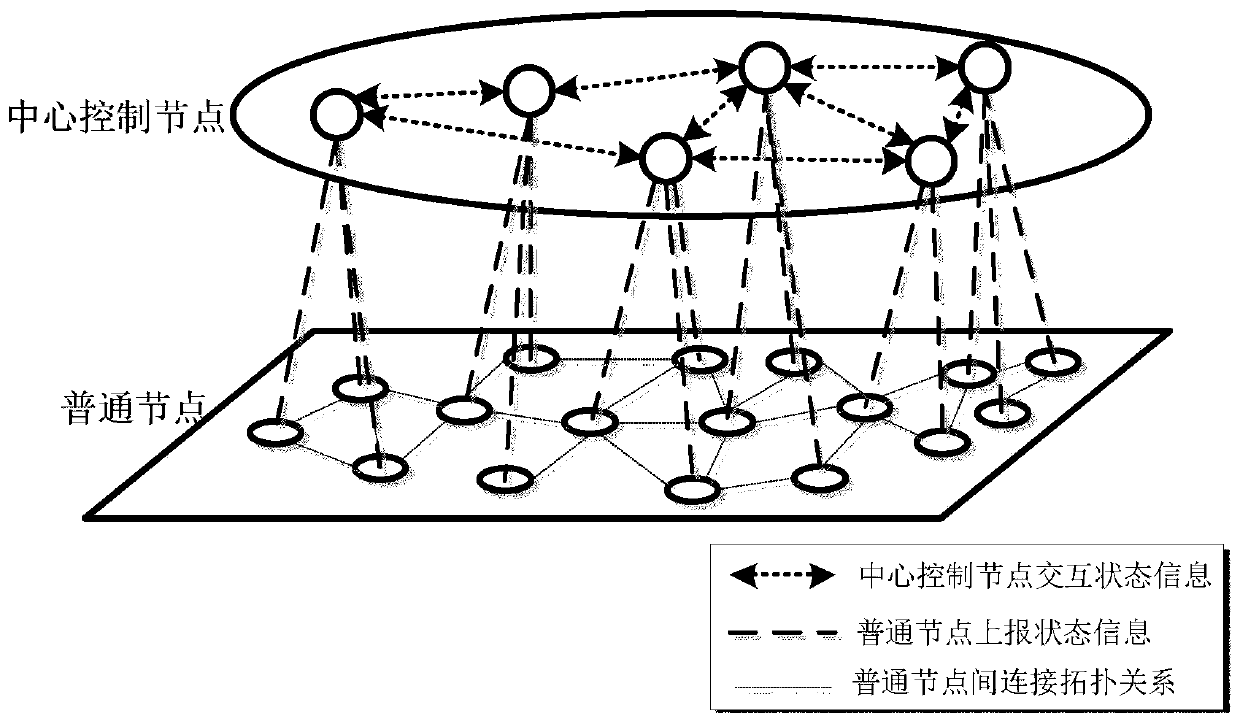
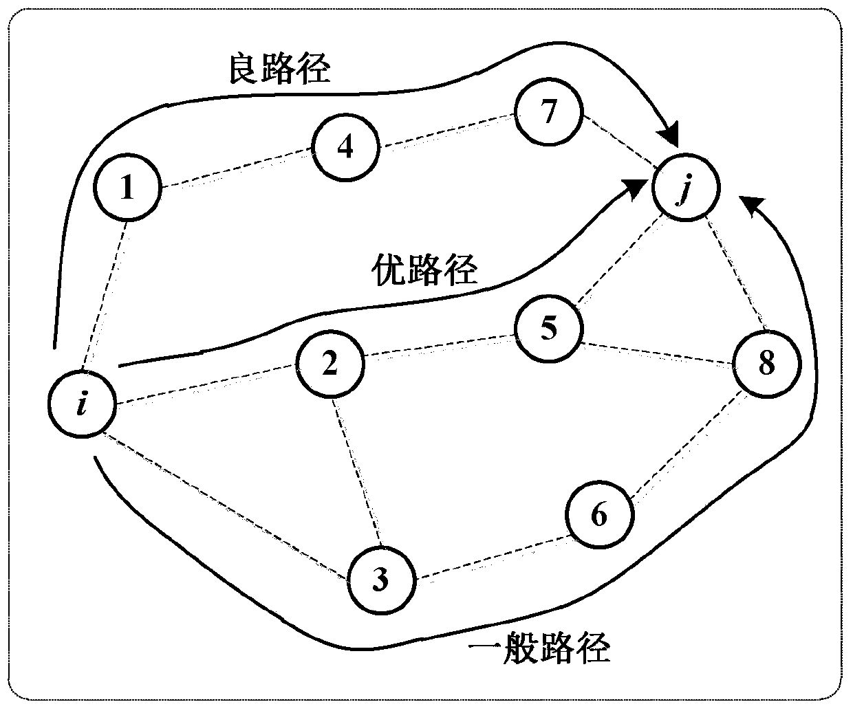
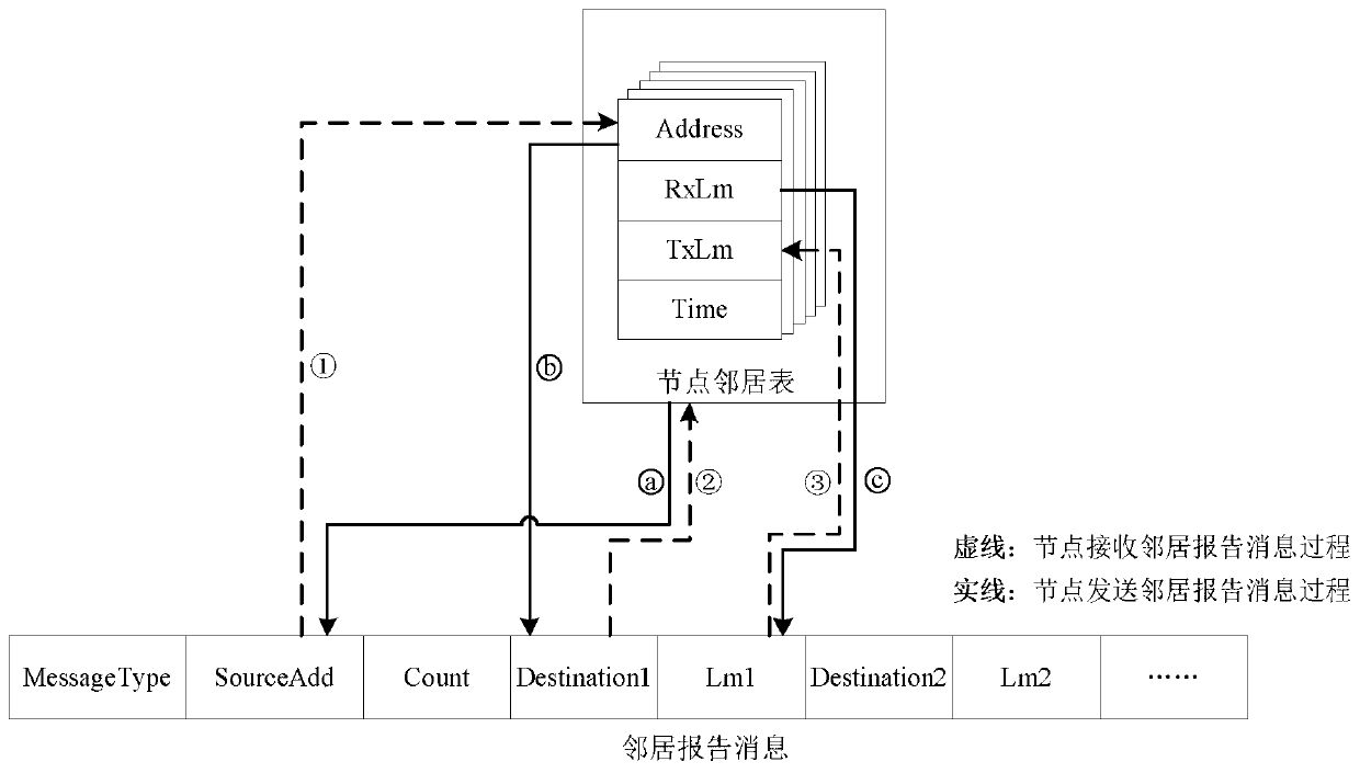
[0020] refer to figure 1 , figure 2 . According to the present invention, the software-defined network (Software Defined Network, SDN) idea is adopted, and the nodes of the whole network are divided into a central control node that manages and maintains the network status information of the whole network and a common node that reports status information, and the control functions of the network and The forwarding function is separated, and then all the control functions are concentrated on the remote central control node, while ordinary nodes only need to be responsible for simple and high-speed data forwarding locally according to the forwarding strategy generated by the central control node. The central control node generates the optimal path from the source node to the destination node, and sends it to common nodes through the control channel. According to the neighbor discovery mechanism, each ordinary node periodically feeds back the node neighbor table information, it...


PUM


Abstract

The invention provides a routing method for minimizing transmission delay of a high-dynamic delay network, and aims to control network congestion with flexible low-overhead network configuration. Themethod is realized through the following technical scheme: whole network nodes are divided into central control nodes and common nodes by adopting a software defined network (SDN); the central controlnode generates an optimal path from the source node to the destination node and sends the optimal path to the common node through the control channel; each common node periodically feeds back node neighbor table information, topology connection information of the common node and node flow state information to the central control node through the control channel according to a neighbor discovery mechanism; the central control node obtains whole network view information in a continuous iteration mode; when a data packet needs to be forwarded, the common node completes data packet forwarding according to a routing table instruction issued by the central control node; and the central control node judges whether the network is congested or not according to the collected node flow information,and distributes and bypasses the data packet in a distribution and bypassing manner to alleviate the network congestion.

Description

technical field [0001] The invention belongs to the technical field of wireless communication, and in particular relates to an effective routing method suitable for solving transmission delay and congestion control in a high-speed and high-dynamic network environment. Background technique [0002] With the increase of the scale of the Internet and the improvement of technology, the needs of users for the network have also undergone corresponding changes. The services that the network can provide have been greatly different from those in the initial stage of network development. With the continuous increase of people's demand for information acquisition, mobile communication technology plays a vital role in wireless communication. Ad hoc network is a multi-hop autonomous network composed of a group of mobile devices with wireless transceivers. The wireless network can be classified according to the structure in a broad sense, and can be divided into a centered network (Infr...

Claims


Application Information

Patent Timeline
Patent Type & Authority Applications(China)
IPC IPC(8): H04W28/02H04W40/02H04W40/04H04W40/12H04W84/18H04L12/707H04L12/721H04L12/741H04L12/759H04L45/24H04L45/28H04L45/74
CPCH04W28/0289H04W84/18H04W28/0284H04W40/02H04W40/04H04L45/124H04L45/24H04L45/54H04L45/028H04W40/12
Inventor 肖磊杜俊逸乔文昇黄秀琼王立
Owner 10TH RES INST OF CETC
Learn More