Supercharge Your Innovation With Domain-Expert AI Agents!

A kind of antenna and network equipment

An antenna and equipment technology, applied in the field of array antennas and network equipment, can solve the problem of small beam width variation range and so on

Active Publication Date: 2021-01-05
HUAWEI TECH CO LTD
View PDF13 Cites 0 Cited by
  • Summary
  • Abstract
  • Description
  • Claims
  • Application Information

AI Technical Summary

Problems solved by technology

However, since adjusting the sides of the reflector has less effect on the current distribution, the range of variation in the beamwidth is smaller

Method used


Image

  • A kind of antenna and network equipment
  • A kind of antenna and network equipment
  • A kind of antenna and network equipment

Examples


Embodiment 1

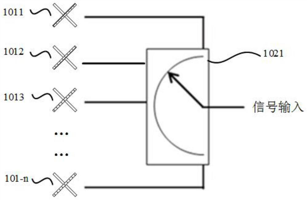
[0065] Figure 1a It is a schematic diagram of an array antenna provided in Embodiment 1 of the present application. Such as Figure 1a As shown, the array antenna includes:

[0066] n radiation units, such as radiation unit 1011, radiation unit 1012, radiation unit 1013, ..., radiation unit 101-n;

[0067] A feed network, the feed network includes a switch 1021, and the switch 1021 is connected to the n radiation units.

[0068] Based on the above structure, the number of the radiation units in the working state can be set by switching the switch 1021 to control the on or off of the signal output from the feed network to the n radiation units, that is, to set different working mode, so as to flexibly change the beamwidth of the antenna radiation pattern. Wherein, the n radiating units may be single-polarized radiating units or dual-polarized radiating units, and the balun corresponding to each polarization direction of the radiating unit has a corresponding feed network to ...

Embodiment 2

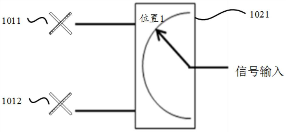
[0083] The array antenna includes two radiating units (respectively radiating unit 1011 and radiating unit 1012), a feed network, and a switch 1021 is included in the feed network, and the two working modes set by the switch are as follows: Figure 2a with Figure 2b shown.

[0084] Figure 2a It is a schematic diagram of the operation of one radiation unit controlled by a switching switch in the second embodiment. Such as Figure 2a As shown, when the switch is switched to position 1, the signal output to the radiation unit 1011 through the feed network is turned on, while the signal output to the radiation unit 1012 is disconnected. In this case, the radiation unit 1011 is in the working state , while the radiation unit 1012 is in a non-working state.

[0085] Figure 2b It is a schematic diagram of the operation of two radiation units controlled by switching switches in the second embodiment. Such as Figure 2b As shown, when the switch is switched to position 2, the...

Embodiment 3

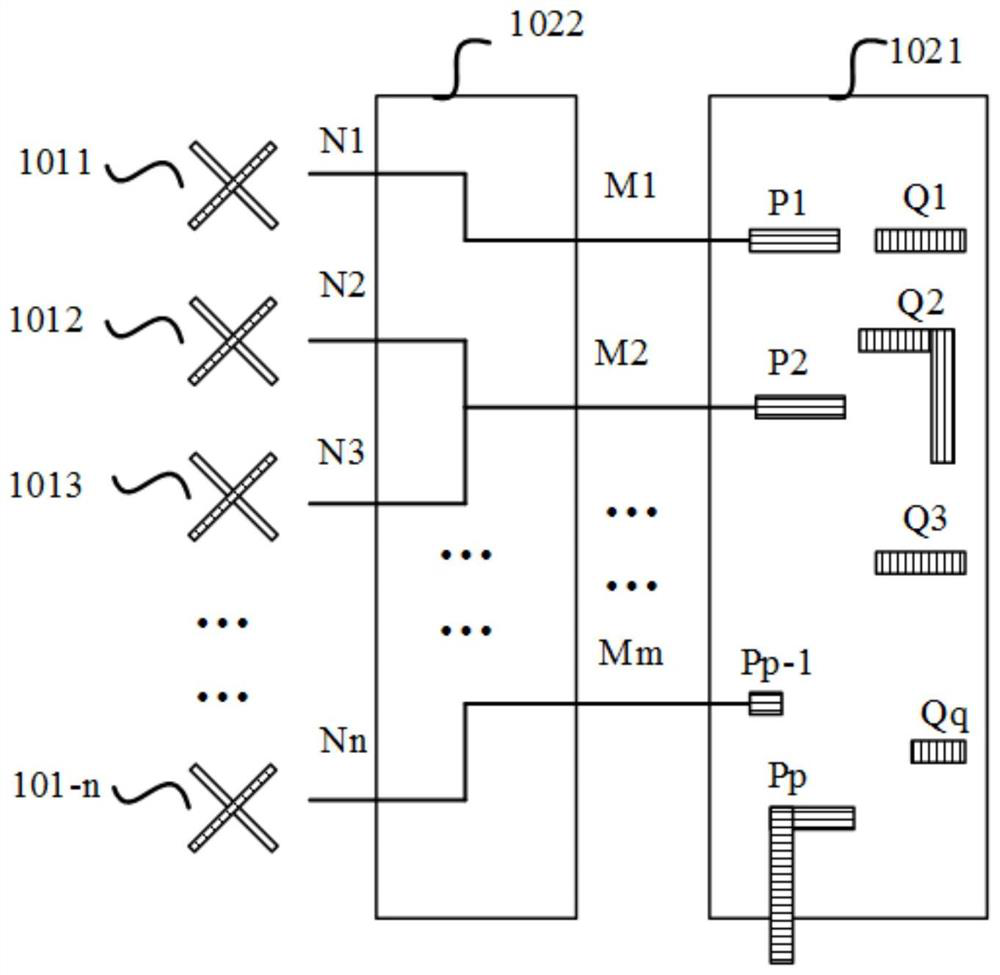
[0095] The array antenna includes two radiating units (respectively radiating unit 1011 and radiating unit 1012), a feed network, including a switch 1021 and a phase shifter 1022 in the feed network, and two working modes set by the switch Such as Figure 3a with Figure 3b As shown, by changing the phase of the phase shifter, the direction of the antenna beam can be changed. The phase shifter can change the phase by changing the dielectric constant of the signal channel, or can change the phase by changing the physical length of the signal channel, or can also adopt other implementation methods.

[0096] Figure 3a It is a schematic diagram of the operation of one radiation unit controlled by a switching switch in the third embodiment. Such as Figure 3a As shown, when the switch is switched to position 1, the signal output to the radiation unit 1011 through the feed network is turned on, while the signal output to the radiation unit 1012 is disconnected. In this case, th...


PUM


Abstract

An array antenna and network equipment, the array antenna includes n radiation units, a power divider or phase shifter, and a switch; the power divider or phase shifter includes n output terminals and m input terminals; the switch includes m The first port, K ​​second ports and switching elements; the m first ports are respectively connected to the m input terminals; the K second ports are used to couple the input signal; the switching element is used to switch the m first ports and K The connection relationship between the second ports enables the input signal to be selectively output to at least one first port. In this application, the switch is used to control the on or off of the signal output to the n radiation units, and the number of radiation units in the working state is set, so as to realize the flexible change of the beam width of the antenna radiation pattern, and because the radiation unit is set The switching switch in the working state or the non-working state has a simple structure, and the insertion loss introduced is small, so the gain of the antenna is high.

Description

technical field [0001] The present application relates to the technical field of antennas, and in particular to an array antenna and network equipment. Background technique [0002] With the development of mobile communication technology, users have higher and higher requirements for high-speed data transmission. At the same time, the types of user needs are becoming more and more diverse. Modern mobile communication needs to meet the requirements of high-speed wireless access in diverse scenarios. The replacement speed of mobile communication equipment is gradually accelerating, but it is becoming more and more difficult to obtain available site resources in urban areas. Therefore, base station antennas that can meet the needs of a variety of sites and have diverse scene working capabilities have become one of the future development directions of base station antennas. . The base station antenna with the ability to work in a variety of scenarios also provides a more effect...

Claims


Application Information

Patent Timeline
IPC IPC(8): H01Q3/24
CPCH01Q3/24H01Q21/0006H01Q25/002H01Q1/246H01P1/127H01Q1/38H01Q3/247H01Q3/38H04W16/28
Inventor 王乃彪肖伟宏
Owner HUAWEI TECH CO LTD
Features
  • R&D
  • Intellectual Property
  • Life Sciences
  • Materials
  • Tech Scout
  • Unparalleled Data Quality
  • Higher Quality Content
  • 60% Fewer Hallucinations
Learn More