Soil remediation agent and soil remediation method and device
A soil remediation agent and soil remediation technology, which is applied in the fields of site preparation method, fertilization device, transportation and packaging, etc., can solve the problems of single efficacy, difficulty in use, complicated preparation of soil remediation agent, etc., and achieve simple preparation process and easy acquisition of preparation raw materials Effect
- Summary
- Abstract
- Description
- Claims
- Application Information
AI Technical Summary
Problems solved by technology
Method used
Image
Examples
Embodiment 1
[0037] A soil remediation agent and a soil remediation method, comprising the following steps;
[0038] S1. After collecting farmyard manure, remove stones and other sundries, spread it on a clean concrete floor, and let it dry naturally under natural ventilation;
[0039] S2. Spread the farmyard manure after the drying treatment in S1 on a drying tray, put it into a hot air oven and dry it at 105° C. for 3 hours;
[0040] S3, put the farmyard manure preheated in S2 into a crucible vessel, put it into a muffle furnace, and control the heating rate to 100 -500 , when the pyrolysis temperature is 200°C-700°C, the pyrolysis time is 0.5-3h under the condition of anoxic; cool to below 80°C with the muffle furnace door closed, and take the crucible-like utensils out of the muffle furnace Cool in a desiccator for later use;
[0041] S4, putting the farmyard manure biochar prepared by pyrolysis in S3 into a pulverizer for crushing, sieving, and taking 20-40 mesh of farmyard manure...
Embodiment 2
[0049] Embodiment 2: Based on Embodiment 1 but different;
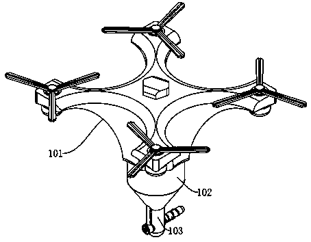
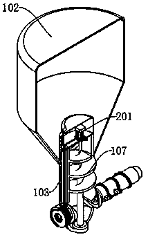
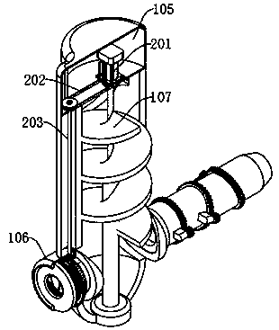
[0050] A soil remediation device, applied to a soil remediation agent and a soil remediation method, comprising: a flying platform 101, a storage bin 102, and a main body feeding shell 103, the lower end of the flying platform 101 is fixedly connected to the upper end of the storage bin 102, and the storage bin The inner wall of the lower end of 102 is fixedly connected with the middle part of the main body feeding shell 103, and the left and right sides of the upper end of the main body feeding shell 103 are provided with feeding ports 104, and the upper end of the main body feeding shell 103 is provided with a power bin 105, and a driving mechanism is fixedly installed inside the power bin 105 , the front side of the lower end of the main body feed shell 103 is fixedly connected with the rear end of the air intake fixed shell 106, the inside of the air intake fixed shell 106 is fixedly installed with an air intake op...
Embodiment 3
[0054] Embodiment 3: based on embodiment 1 and 2 but different;
[0055] The swing discharge mechanism includes: feed fixed pipe 401, first-stage pipe 402, second-stage pipe 403, discharge pipe 404, motor fixed casing 405, small motor 406, gear 407 and rack ring 408, the lower end of the main body feed casing 103 The rear side is fixedly connected with the right end of the feed fixed pipe 401, and a small fan is fixedly installed inside the feed fixed pipe 401. Flexible connection, the left end of the second-stage pipe 403 is movably connected with the right end of the discharge pipe 404, the outer side of the right end of the first-stage pipe 402, the second-stage pipe 403 and the discharge pipe 404 is provided with a rack ring 408, the feed fixed pipe 401, the first-stage pipe 402 and second-stage tube 403 are fixedly installed with a motor fixed shell 405 on the outside of the upper middle part, and a small motor 406 is fixedly installed inside the motor fixed shell 405, an...
PUM
 Abstract
Description
Claims
Application Information
 - R&D Engineer
- R&D Manager
- IP Professional
- Industry Leading Data Capabilities
- Powerful AI technology
- Patent DNA Extraction
Browse by: Latest US Patents, China's latest patents, Technical Efficacy Thesaurus, Application Domain, Technology Topic, Popular Technical Reports.
© 2024 PatSnap. All rights reserved.Legal|Privacy policy|Modern Slavery Act Transparency Statement|Sitemap|About US| Contact US: help@patsnap.com


