Multilayer assembled electric furnace hearth

An assembled electric furnace technology, applied in the furnace, furnace, furnace bottom, etc., can solve the problems of high radial heat radiation and heat conduction of the electric furnace, increase the use and maintenance cost of the electric furnace, reduce the service life of the furnace, etc., to improve the production environment, The effect of shortening the production cycle and reducing maintenance costs

Pending Publication Date: 2019-08-20
SUZHOU DINGAN ELECTRONICS TECH
View PDF0 Cites 0 Cited by
  • Summary
  • Abstract
  • Description
  • Claims
  • Application Information

AI Technical Summary

Problems solved by technology

[0003] The hearth of the experimental electric furnace is usually obtained by integral extrusion or grouting of heavy high-temperature refractory materials and then fired at high temperature. The disadvantages are large thermal conductivity, large heat capacity and low yield.
At the same time, due to thermal expansion at the initial stage of use of this kind of integral furnace, especially when the heating or cooling rate is fast, the overall temperature of the furnace is uneven or the thermal stress is too large, resulting in deformation or even cracking of the furnace, reducing the service life of the furnace; while the integrity of the traditional furnace The structure makes it difficult to remove the exhaust gas when the item is heated, which has a corrosive effect on the electric heating element, thus increasing the use and maintenance costs of the electric furnace
[0004] To this end, it is necessary to solve the problem of high radial heat radiation and heat conduction in the existing electric furnace, which is not conducive to energy saving. It is necessary to reasonably design the furnace structure of the experimental electric furnace, so as to provide a method that can ensure the effective release of thermal stress and can smoothly discharge the exhaust gas in the furnace. Emission, experimental electric furnace furnace with better energy saving effect

Method used


Image

  • Multilayer assembled electric furnace hearth
  • Multilayer assembled electric furnace hearth
  • Multilayer assembled electric furnace hearth

Examples


Embodiment Construction

[0025] The present invention will be further described below in conjunction with the accompanying drawings and embodiments.

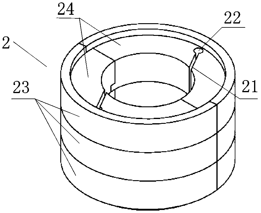
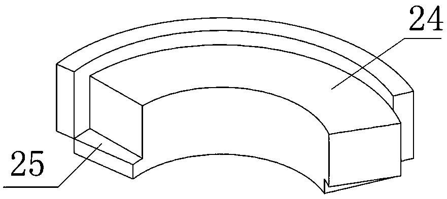
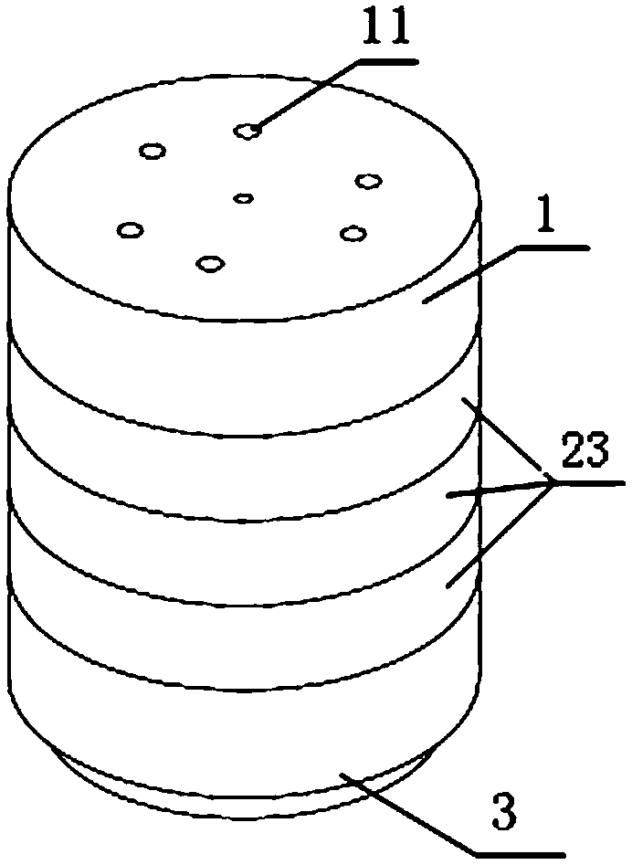
[0026] Such as image 3 , Figure 4 Shown is the multi-layer assembled type electric furnace hearth of the present invention, it comprises, ring-shaped furnace wall 2, and furnace roof 1 and furnace bottom 3 respectively positioned at the upper and lower sides of described furnace wall 2, the present invention is according to bell jar type, lifting According to the actual situation of electric furnace and pit type experimental electric furnace, the positions of furnace top 1 and furnace bottom 3 can be interchanged, image 3 It is suitable for the hearth of a bell-type or lift-type experimental electric furnace, the furnace roof 1 is located on the upper side, and the furnace bottom 3 is located on the lower side, Figure 4 To be suitable for the hearth of a well-type experimental electric furnace, the furnace roof 1 is located on the lower side, and ...


PUM


Abstract

The invention discloses a multilayer assembled electric furnace hearth which comprises an annular furnace wall (2), and a furnace cover (1) and a furnace bottom (2) located on the upper side and the lower side of the furnace wall (2). At least one heat expansion seam (21) and at least one exhaust hole (22) are formed in the furnace wall (2), and penetrate through the furnace wall (2) along a height direction of the furnace wall (2); and the heat expansion seam (21) extends onto the exhaust hole (22) in the direction from the inner wall of the furnace wall (2) to the outer wall. According to the electric furnace hearth, on one hand, the requirement on heat expansion of an inner circle of the furnace wall on a middle layer located at a high temperature area in the temperature rise process ofthe hearth is met, so that the heat stress is ensured to be effectively released; on the other hand, through the heat expansion seam and the exhaust hole communicating with the heat expansion seam, awaste gas in the hearth can be smoothly exhausted; and in addition, the radial heat radiation and heat conduction of the hearth can be prevented, so that an energy-saving effect of the hearth is improved.

Description

technical field [0001] The invention relates to the technical field of electric furnace manufacturing, in particular to a multi-layer assembled electric furnace hearth for experimental electric furnaces. Background technique [0002] Experimental electric furnaces are mostly used in experiments and small batch production in universities, industrial and mining enterprises. The furnace body of the experimental electric furnace includes a shell, a furnace and an insulation layer between the shell and the furnace. An electric heating element is installed in the furnace, and the electric energy is converted into heat energy through the electric heating element to heat the items in the furnace. The higher the temperature in the furnace, the higher the temperature. The thickness of the furnace wall is thicker. [0003] The hearth of the experimental electric furnace is usually obtained by integral extrusion or grouting of heavy high-temperature refractory materials and then fired ...

Claims


Application Information

Patent Timeline
Patent Type & Authority Applications(China)
IPC IPC(8): F27D1/00F27B17/02
CPCF27B17/02F27D1/0043
Inventor 李亚军朱阳光李亚东徐传艳
Owner SUZHOU DINGAN ELECTRONICS TECH
Why Eureka
Try Eureka