Milling cutter breakage detection method and device based on permanent-magnet disturbance probe and application

A permanent magnet disturbance and damage detection technology, which is used in measuring/indicating equipment, metal processing equipment, metal processing mechanical parts, etc. It can solve the problem of indirect measurement time, many influencing factors, difficult to obtain the shape of the milling cutter, and harsh detection conditions. and other problems, to achieve the effect of loose detection conditions, convenient repeated detection, and simple detection

Active Publication Date: 2019-08-23
HUAZHONG UNIV OF SCI & TECH
View PDF10 Cites 1 Cited by
  • Summary
  • Abstract
  • Description
  • Claims
  • Application Information

AI Technical Summary

Problems solved by technology

Specifically, direct measurement mainly includes: resistance measurement method, tool workpiece distance measurement method, ray measurement method, microstructure coating method, optical measurement method, discharge current measurement method, computer image processing method, etc.; but these methods often require detection Harsh conditions or complicated preparations lead to a narrow range of practical applications
Indirect measurements include: cutting force detection method, acoustic emission detection method, power signal detection method, vibration signal detection method, cutting temperature measurement method, current signal measurement method, thermal voltage measurement method, workpiece surface roughness measurement method, etc.; but due to indirect There are many indirect influencing factors during measurement, and it is difficult to obtain features directly related to the appearance of the milling cutter, resulting in low detection accuracy

Method used


Image

  • Milling cutter breakage detection method and device based on permanent-magnet disturbance probe and application
  • Milling cutter breakage detection method and device based on permanent-magnet disturbance probe and application
  • Milling cutter breakage detection method and device based on permanent-magnet disturbance probe and application

Examples


Embodiment Construction

[0036] In order to make the object, technical solution and advantages of the present invention clearer, the present invention will be further described in detail below in conjunction with the accompanying drawings and embodiments. It should be understood that the specific embodiments described here are only used to explain the present invention, not to limit the present invention. In addition, the technical features involved in the various embodiments of the present invention described below can be combined with each other as long as they do not constitute a conflict with each other.

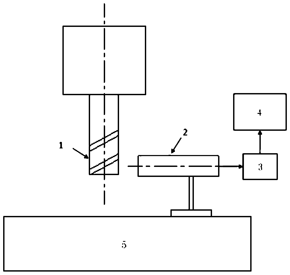
[0037] Such as figure 1 As shown, a milling cutter damage detection method based on a permanent magnet disturbance probe provided in an embodiment of the present invention includes the following steps:

[0038] S1 The milling cutter 1 to be tested rotates at a preset speed so that the permanent magnet disturbance probe 2 on its side generates a signal, and the signal of the permanent magnet dis...


PUM


Abstract

The invention belongs to the field related to numerical control machining tool detection, and discloses a milling cutter breakage detection method and device based on a permanent-magnet disturbance probe and application. The permanent-magnet disturbance probe of which the axis is perpendicular to and coplanar with the axis of a to-be-detected milling cutter is arranged beside the to-be-detected milling cutter, then the to-be-detected milling cutter rotates according to the preset rotation speed to enable the permanent-magnet disturbance probe to generate signals, the signals of the permanent-magnet disturbance probe are collected, and the collected signals are processed to judge whether the to-be-detected milling cutter is broken or not. The milling cutter breakage detection method and device can be applied to a milling machining method and system in order to achieve milling cutter breakage detection in the milling machining process and have the advantages of being accurate in detection, convenient to operate, wide in applicability and the like.

Description

technical field [0001] The invention belongs to the related field of CNC machining tool detection, and more specifically relates to a milling cutter damage detection method, device and application based on a permanent magnet disturbance probe. Background technique [0002] With the continuous improvement of the degree of automation and intelligence in the manufacturing industry, in the process of CNC machining, the requirements for the monitoring technology of the cutting process are also getting higher and higher. Especially in the process of intermittent milling, the breakage of the milling cutter often occurs, which may lead to the scrapping of parts, and may cause damage to the machine tool, so it is necessary to detect the breakage of the milling cutter. [0003] At present, there are two types of detection for milling cutters: direct measurement and indirect measurement. Specifically, direct measurement mainly includes: resistance measurement method, tool-workpiece di...

Claims


Application Information

Patent Timeline
Patent Type & Authority Applications(China)
IPC IPC(8): B23Q17/09
CPCB23Q17/0957
Inventor 何岭松陈吉红王向阳高志强
Owner HUAZHONG UNIV OF SCI & TECH
Why Eureka
Try Eureka