
Pre-weld and post-weld heat treatment methods for inertial friction welded rotor assemblies

A technology of inertial friction welding and post-weld heat treatment, applied in the field of inertial friction welding, which can solve the problems of microstructure growth, mechanical properties, and decline

Active Publication Date: 2020-06-16
AECC COMML AIRCRAFT ENGINE CO LTD
View PDF7 Cites 1 Cited by
  • Summary
  • Abstract
  • Description
  • Claims
  • Application Information

AI Technical Summary

Problems solved by technology

[0010] The technical problem to be solved by the present invention is to overcome the defect that the microstructure grows up and the mechanical properties drop easily caused by the inertia friction welding rotor assembly before and after welding in the prior art, and provides a kind of inertia friction welding rotor assembly before and after welding. Post-weld heat treatment method

Method used


Image

  • Pre-weld and post-weld heat treatment methods for inertial friction welded rotor assemblies

Examples


Embodiment Construction

[0034] In order to make the above objects, features and advantages of the present invention more comprehensible, specific implementations of the present invention will be described in detail below in conjunction with the accompanying drawings.

[0035] Embodiments of the present invention will now be described in detail with reference to the accompanying drawings. Reference will now be made in detail to the preferred embodiments of the invention, examples of which are illustrated in the accompanying drawings. Wherever possible, the same numbers will be used throughout the drawings to refer to the same or like parts.

[0036] In addition, although the terms used in the present invention are selected from well-known and commonly used terms, some terms mentioned in the description of the present invention may be selected by the applicant according to his or her judgment, and the detailed meanings thereof are set forth herein described in the relevant section of the description. ...


PUM

PropertyMeasurementUnit
tensile strengthaaaaaaaaaa

Abstract

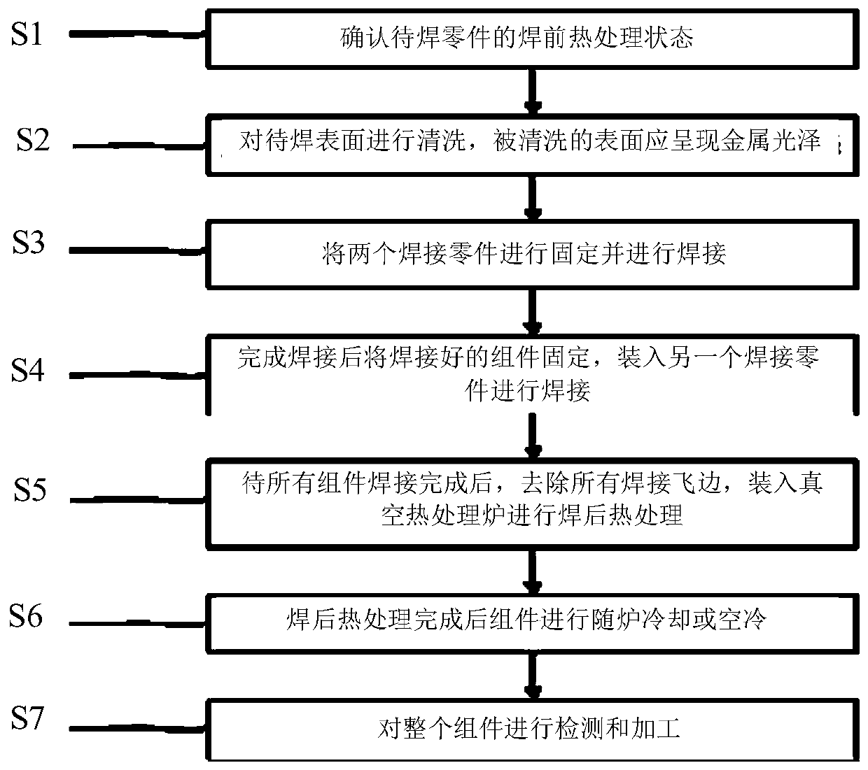
The invention provides a heat treatment method of an inertia friction welding rotor module before and after welding. The method comprises the following steps: (1) a before-welding heat treatment stateof parts to be welded is determined; (2) the surfaces of all the parts to be welded are cleaned; and the cleaned surfaces show the metal luster; (3) two welded parts are fixed and welded; (4) weldedmodules are fixed after welding, and are loaded in another welded part for welding; (5) all welding flanges are removed after the module welding, and are loaded in a vacuum heat treatment furnace forafter-welding heat treatment; (6) the air cooling or the atmosphere cooling is performed on the modules after the after-welding heat treatment; and (7) all inertia friction welding rotor modules are detected and machined. On the basis of guaranteeing material structures and performances, the unified after-welding heat treatment regime of the modules is guaranteed, and the support is provided for application of the inertia friction welding process to aero-engine welding robot modules.

Description

technical field [0001] The invention relates to inertial friction welding of a high-pressure compressor rotor assembly and a high-pressure turbine disk shaft assembly, in particular to a pre-welding and post-welding heat treatment method for an inertial friction welding rotor assembly. Background technique [0002] During inertial friction welding, the energy required is mainly provided by the rotational kinetic energy stored in the flywheel of the welding machine. Before the inertia friction welding starts, the workpieces to be welded are respectively loaded into the rotating end of the flywheel and the fixed sliding end of the welding machine. When welding starts, the flywheel and rotating parts are accelerated to a predetermined speed, then the flywheel is disengaged from the power source (generally the main drive motor or hydraulic motor), and the slip end parts move forward. When the parts are in contact, the two welded end faces start to frictionally heat. As the fly...

Claims


Application Information

Patent Timeline
Patent Type & Authority Patents(China)
IPC IPC(8): C22F1/10C21D9/50B23K20/24B23K37/00
CPCB23K20/24B23K37/00C21D9/50C22F1/10
Inventor 张露韩秀峰王伦蔡拓阮雪茜
Owner AECC COMML AIRCRAFT ENGINE CO LTD
Learn More