Single-tank closed circulation energy storage power generation system

A closed cycle, power generation system technology, applied in the field of energy storage, can solve problems such as increasing the temperature of the second heat storage body, and achieve the effects of ensuring energy conversion efficiency, smoothing instability, and stable temperature difference

Pending Publication Date: 2019-08-23
STATE POWER INVESTMENT CORP RES INST
View PDF10 Cites 2 Cited by
  • Summary
  • Abstract
  • Description
  • Claims
  • Application Information

AI Technical Summary

Problems solved by technology

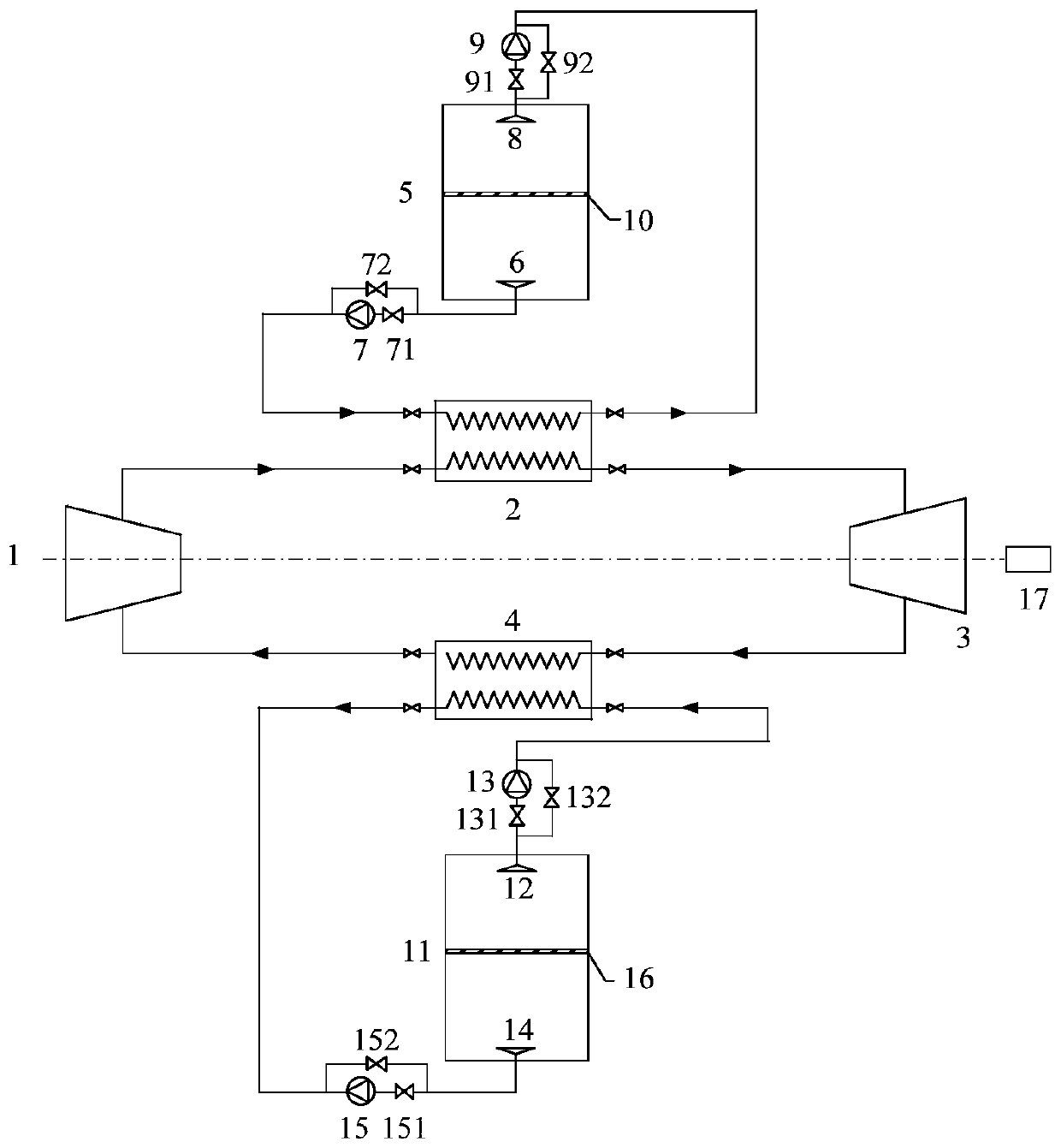
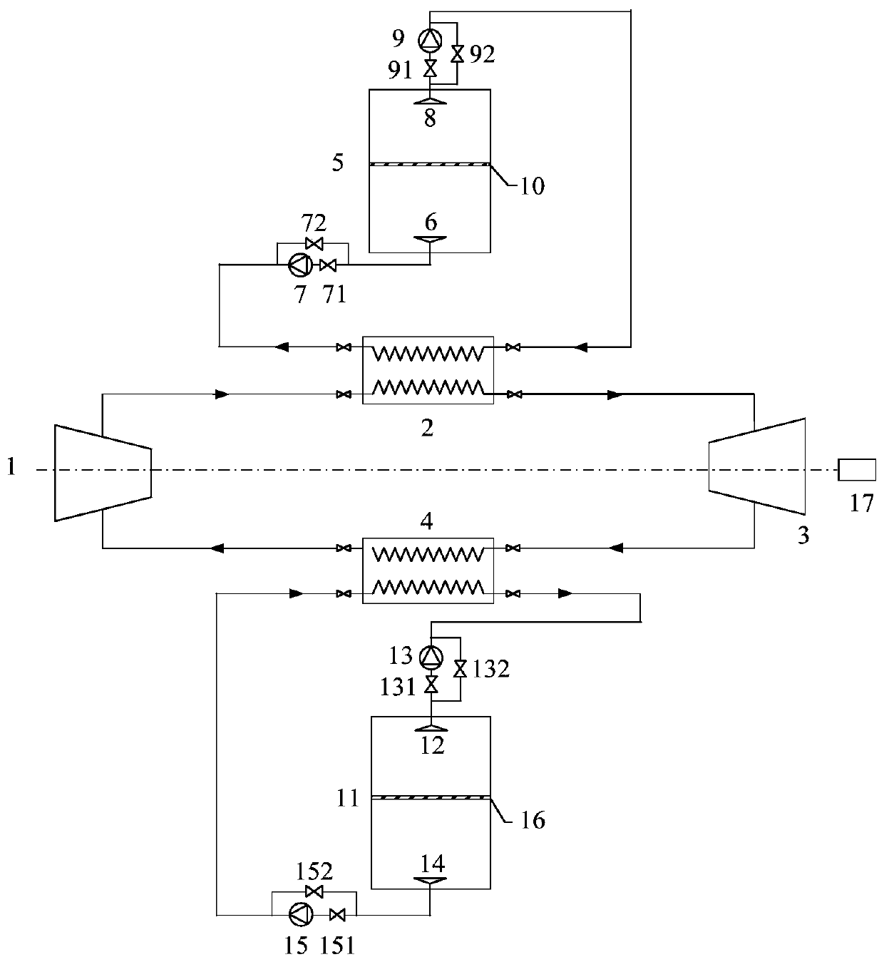
[0004] However, the above technical solutions have the following defects: the cycle mode of energy storage (electricity storage) through the normal temperature working medium is: compression-heat release (through the second heat storage body)-expansion work-heating-heat absorption (through the first heat storage body); the cycle mode of power supply is: compression - heat absorption (through the second heat storage body) - expansion work - heat release (through the first heat storage body) - heating
In the energy storage circulation mode, if a single-tank energy storage is used, the heat and cooling capacity cannot be fully stored; if a double-tank energy storage is used, the heat and cooling capacity can be fully stored; in the power supply cycle mode, in order to maintain the high-temperature heat source The temperature difference and energy conversion efficiency between the second regenerator and the first regenerator as a low-temperature heat source need to increase the temperature of the second regenerator; the system is an open cycle, when the circulating working medium is helium, argon and other gases not applicable

Method used


Image

  • Single-tank closed circulation energy storage power generation system
  • Single-tank closed circulation energy storage power generation system

Examples


Embodiment Construction

[0023] Embodiments of the present invention are described in detail below, examples of which are shown in the drawings, wherein the same or similar reference numerals designate the same or similar elements or elements having the same or similar functions throughout. The embodiments described below by referring to the figures are exemplary only for explaining the present invention and should not be construed as limiting the present invention.

[0024] In describing the present invention, it should be understood that the terms "center", "longitudinal", "transverse", "upper", "lower", "front", "rear", "left", "right", " The orientations or positional relationships indicated by "vertical", "horizontal", "top", "bottom", "inner" and "outer" are based on the orientations or positional relationships shown in the drawings, and are only for the convenience of describing the present invention and Simplified descriptions, rather than indicating or implying that the device or element refe...


PUM


Abstract

The invention provides a single-tank closed circulation energy storage power generation system. The single-tank closed circulation energy storage power generation system comprises a fused salt tank, an anti-freezing solution tank, a compressor, first / second heat exchangers, a turbine, upper / lower fused salt distributors, a low-temperature fused salt pump, a high-temperature fused salt pump, a fused salt thermocline, upper / lower anti-freezing solution distributors, a high-temperature anti-freezing solution pump, an anti-freezing solution pump, an anti-freezing solution thermocline, an engine and multiple valves. By selectively switching on one or more of the fused salt tank, the anti-freezing solution tank, the compressor, the first / second heat exchangers, the turbine, the upper / lower fusedsalt distributors, the low-temperature fused salt pump, the high-temperature fused salt pump, the fused salt thermocline, the upper / lower anti-freezing solution distributors, the high-temperature anti-freezing solution pump, the anti-freezing solution pump, the anti-freezing solution thermocline, the multiple valves and the engine, heat energy and electric energy are mutually converted. Stable output of renewable energy electricity such as wind power or photovoltaic power generation can be achieved, the effect of balancing electricity supply and demand is achieved, large-scale energy storagecan be achieved, the advantage of energy storage peak regulating is exerted, and a response is made to the requirements of renewable energy storage.

Description

technical field [0001] The invention relates to the technical field of energy storage, in particular to a single-tank closed cycle energy storage power generation system. Background technique [0002] The molten salt heat storage technology is to heat the molten salt through electric energy, solar energy and other energy sources in the heat storage stage, and store the heat in the high-temperature molten salt. In the heat supply stage, heat is released through high-temperature molten salt, and high-temperature molten salt releases heat to heat users through heat exchange. The heat released is in the form of supplying steam, driving steam turbines to generate electricity through supplying steam, and supplying heat, etc., which can be applied to light Energy storage systems such as heat storage in thermal power plants, peak shaving in thermal power plants, power consumption of renewable energy such as abandoned wind and light, and utilization of low-peak electricity play a rol...

Claims


Application Information

Patent Timeline
Patent Type & Authority Applications(China)
IPC IPC(8): F01K27/00F01K25/00F01D15/10F28D20/00
CPCF01K27/00F01K25/00F01D15/10F28D20/0034F28D2020/0047Y02E70/30Y02E60/14
Inventor 张谨奕李京浩王含白宁宗军
Owner STATE POWER INVESTMENT CORP RES INST
Why Eureka
Try Eureka