
Engine tail gas diluting and cooling device based on Bernoulli law and debugging method and adjusting method

A technology of cooling device and engine, which is applied to exhaust devices, engine components, combustion engines, etc., can solve the problems of reducing the exhaust temperature to below the risk factor, dense personnel exchanges, and exhaust temperature restrictions, and achieves a simple and convenient debugging method. , The effect of low exhaust temperature and increasing suction volume

Pending Publication Date: 2019-08-23
PINGYUAN FILTER
View PDF0 Cites 0 Cited by
  • Summary
  • Abstract
  • Description
  • Claims
  • Application Information

AI Technical Summary

Problems solved by technology

However, some special places have strict restrictions on the exhaust temperature, such as mine operations, dust workshop operations, etc.
There is a large amount of combustible dust in relatively closed places such as workshops or mines that contain dust. The high-temperature exhaust gas emitted by the engine may cause fires and explosions, and the closed places are relatively small, with intensive personnel traffic, and the high-temperature exhaust gas emitted by the engine may also cause burns. danger
Traditional cooling methods rely on natural heat convection and heat radiation, and it is difficult to reduce the exhaust temperature below the dangerous factor

Method used


Image

  • Engine tail gas diluting and cooling device based on Bernoulli law and debugging method and adjusting method
  • Engine tail gas diluting and cooling device based on Bernoulli law and debugging method and adjusting method
  • Engine tail gas diluting and cooling device based on Bernoulli law and debugging method and adjusting method

Examples


Embodiment Construction

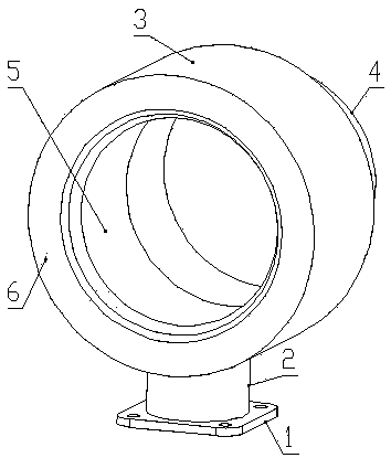
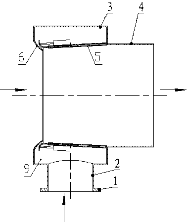
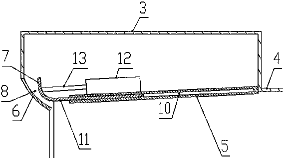
[0055] like Figure 1 to Figure 4 As shown, the engine exhaust dilution and cooling device based on Bernoulli's law of the present invention includes a dilution box 3, the middle part of the side wall of the dilution box 3 is connected with a cooling pipe 4 for exhaust exhaust, and the dilution box 3 is provided with a cooling pipe 4 that communicates with the cooling pipe 4. The diffuser 5 is inwardly directed toward the center of the dilution tank 3, and the side wall of the dilution tank 3 is connected inwardly with a suction port 6 communicating with the atmosphere. The vertical section of the suction port 6 is a horn with a large outside and a small inside. shape; the suction port 6 and the diffuser tube 5 are respectively connected on the opposite side walls of the dilution box 3, and the connection between the suction port 6 and the dilution box 3 is the root of the suction port 6;

[0056] One end of the diffuser 5 facing the suction port 6 is connected with a bell mou...


PUM


Abstract

The invention discloses an engine tail gas diluting and cooling device based on a Bernoulli law. The device comprises a diluting box in diluting connection with a cooling pipe; a flow expanding cylinder communicating with the cooling pipe is arranged in the diluting box; the side wall of the diluting box is inwards connected with a gas sucking port; the end, towards the gas sucking port, of the flow expanding cylinder is connected with a horn port; an annular gap is surrounded between the horn port and the gas sucking port; an intake cavity is surrounded between the flow expanding cylinder andthe diluting box; and the intake cavity is connected with an intake pipe. The invention further discloses a corresponding debugging method and a tail gas adjusting method. Negative pressure can be generated in the annular gap; and environmental air is sucked into the flow expanding cylinder for mixing with exhausted gas of an engine to reduce the exhaust temperature to prevent harm caused by high-temperature tail gas. The stepper debugging method is adopted without needing linear debugging, so that the debugging workload is greatly reduced, and the debugging efficiency is improved. The tail gas adjusting method is provided with three modes to meet the demands in different places.

Description

technical field [0001] The invention relates to the technical field of engine exhaust post-processing technology, in particular to exhaust gas cooling technology. Background technique [0002] The exhaust temperature of the engine is generally between 400°C and 700°C. After being cooled by the traditional exhaust manifold and catalytic muffler, the outlet temperature is also 150°C to 300°C. However, some special places have strict restrictions on the exhaust temperature, such as mine operations, dust workshop operations, etc. There is a large amount of combustible dust in relatively closed places such as workshops or mines that contain dust. The high-temperature exhaust gas emitted by the engine may cause fires and explosions, and the closed places are relatively small, with intensive personnel traffic, and the high-temperature exhaust gas emitted by the engine may also cause burns. danger. Traditional cooling methods rely on natural heat convection and heat radiation, and...

Claims


Application Information

Patent Timeline
Patent Type & Authority Applications(China)
IPC IPC(8): F01N3/05F01N9/00
CPCF01N3/05F01N9/00F01N2270/02Y02T10/40
Inventor 木景坡高冬雪常运来倪雪莉宁家涛邵瑞娜
Owner PINGYUAN FILTER
Learn More