Liquid air separation device and production method utilizing night cheap electric power
A technology of air separation plant and electric power, which is applied in the directions of liquefaction, cold treatment separation, refrigeration and liquefaction, etc., can solve the problem of high production cost of air separation plant, and achieve the effect of avoiding adverse effects, system stability and good cooling effect.
- Summary
- Abstract
- Description
- Claims
- Application Information
AI Technical Summary
Problems solved by technology
Method used
Image

Examples
Embodiment 1
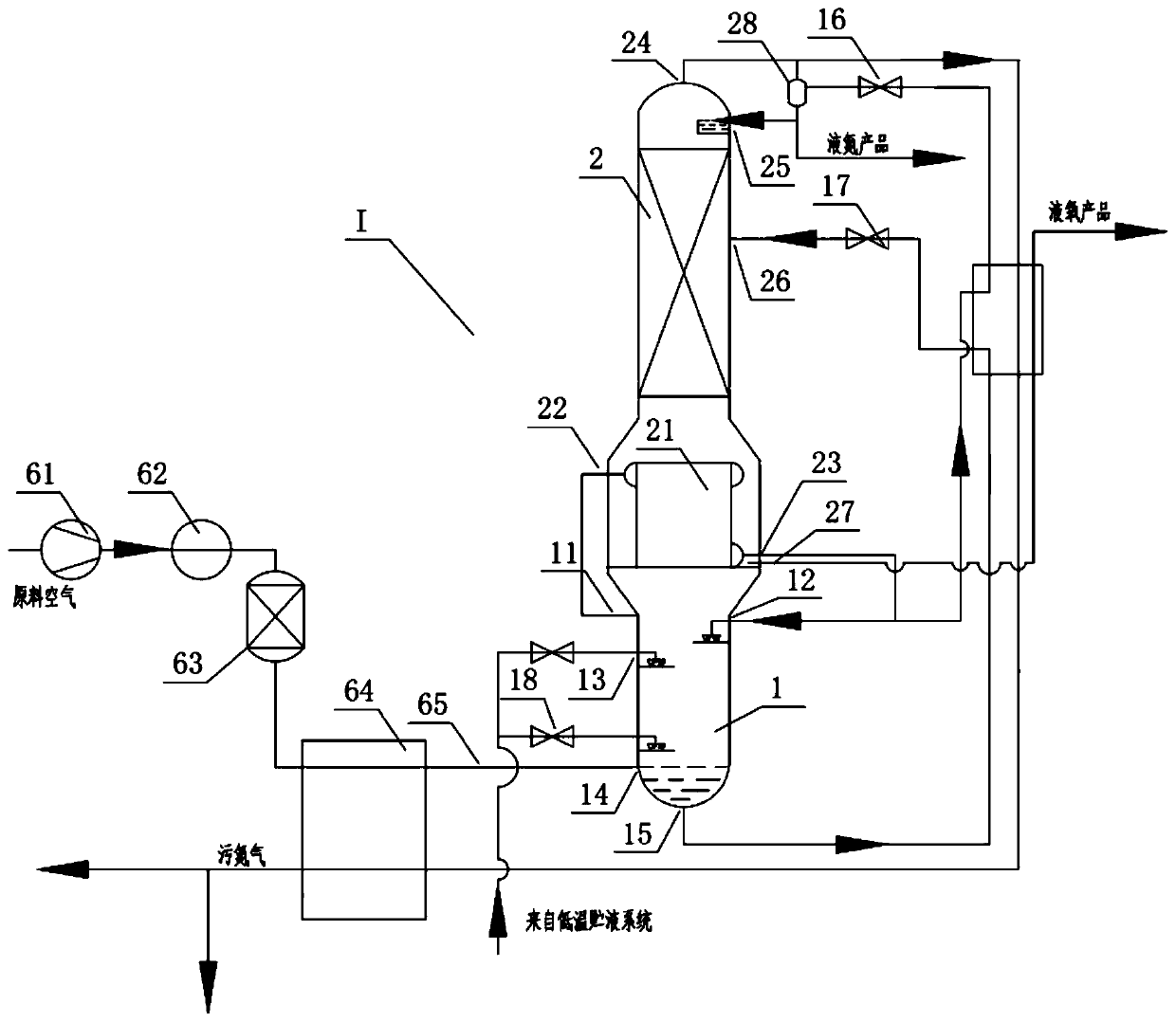
[0032] See attached Figure 1~2 . A liquid air separation plant utilizing cheap electricity at night, comprising a constant operation air separation system I, variable load or intermittent operation liquefaction system II and a cryogenic liquid storage system III; the constant operation air separation system I includes a lower tower 1, an upper tower 2. Main condensing evaporator 21, liquid nitrogen separator 28, throttle valve one 16 and throttle valve three 17; the lower tower 1 at least includes a nitrogen outlet 11, a first reflux liquid inlet 12, and a cryogenic liquid from top to bottom. Inlet 13, compressed cooling and purified air inlet 14 and oxygen-enriched liquid air outlet 15; the main condensation evaporator 21 is located at the bottom of the upper tower 2, including a nitrogen inlet 22 and a liquid nitrogen outlet 23; the upper tower 2 is from top to bottom At least including dirty nitrogen outlet 24, liquid nitrogen inlet 25, oxygen-enriched liquid air inlet 26...
Embodiment 2
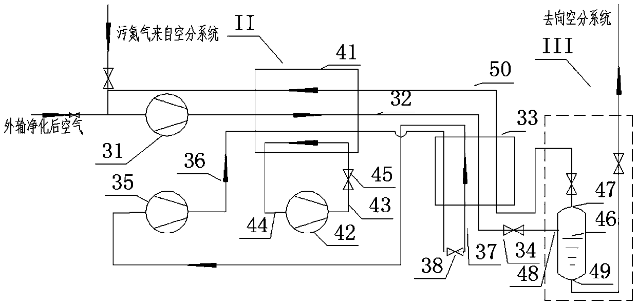
[0040] See attached figure 1 , 3 . A liquid air separation plant utilizing cheap electricity at night, comprising a constant operation air separation system I, variable load or intermittent operation liquefaction system II and a cryogenic liquid storage system III; the constant operation air separation system I includes a lower tower 1, an upper tower 2. Main condensing evaporator 21, liquid nitrogen separator 28, throttle valve one 16 and throttle valve three 17; the lower tower 1 at least includes a nitrogen outlet 11, a first reflux liquid inlet 12, and a cryogenic liquid from top to bottom. Inlet 13, compressed cooling and purified air inlet 14 and oxygen-enriched liquid air outlet 15; the main condensation evaporator 21 is located at the bottom of the upper tower 2, including a nitrogen inlet 22 and a liquid nitrogen outlet 23; the upper tower 2 is from top to bottom At least including dirty nitrogen outlet 24, liquid nitrogen inlet 25, oxygen-enriched liquid air inlet ...
Embodiment 3
[0046] See attached Figure 1~3 . A liquid air separation production method using cheap electricity at night, adopting a liquid air separation device using cheap electricity at night according to claim 8, comprising a constant operation air separation step, a variable load or intermittent operation liquefaction step and low temperature liquid storage step;
[0047] The air separation steps of constant operation are: after the raw air is compressed by the raw air compressor unit 61, it enters the air precooler 62 for cooling, then enters the air purifier 63 to remove impurities that are easy to freeze and block, and then enters the main heat exchanger 64 to be cooled to Saturation temperature, then enter the lower tower 1 from the compressed cooling and purified air inlet 14; the low-temperature liquid storage system III provides low-temperature liquid to enter the middle part of the lower tower 1 from the cryogenic liquid inlet 13, as one of the reflux liquids of the lower to...
PUM
 Abstract
Description
Claims
Application Information
 - R&D Engineer
- R&D Manager
- IP Professional
- Industry Leading Data Capabilities
- Powerful AI technology
- Patent DNA Extraction
Browse by: Latest US Patents, China's latest patents, Technical Efficacy Thesaurus, Application Domain, Technology Topic.
© 2024 PatSnap. All rights reserved.Legal|Privacy policy|Modern Slavery Act Transparency Statement|Sitemap