A power transmission busbar system suitable for high altitude areas

A busbar system, high-altitude technology, applied in the direction of system integration technology, information technology support system, electrical components, etc., can solve problems such as difficult maintenance, many voltage-reducing layers, loss, etc.

Active Publication Date: 2021-04-23
昆明东控电器成套设备有限公司
View PDF6 Cites 0 Cited by
  • Summary
  • Abstract
  • Description
  • Claims
  • Application Information

AI Technical Summary

Problems solved by technology

[0002] In the power system, especially the power system in the plateau area, in the mid-to-long distance transmission, the transmission distance is long, the number of step-down layers is large, and the operation status is greatly affected by the operation mode and power load changes. The corresponding distribution lines The absorbed reactive power is also different, which will cause excessive voltage fluctuations and problems such as overvoltage and harmonics
In different regions and different time periods, the power load of each distribution line in the distribution network is different, and the voltage of the circuit will increase or decrease according to the load. In this case, if no reasonable compensation and adjustment are made, not only will a large amount of power In severe cases, it will lead to the collapse of the power system and cause heavy losses
Moreover, the transportation in the plateau area is inconvenient and the geographical environment is complex, which brings great difficulties to maintenance. Therefore, it is necessary to reasonably configure the power grid to ensure the stability of the voltage in the power grid transmission and achieve the purpose of saving energy and reducing consumption.

Method used


Image

  • A power transmission busbar system suitable for high altitude areas
  • A power transmission busbar system suitable for high altitude areas
  • A power transmission busbar system suitable for high altitude areas

Examples


Embodiment Construction

[0019] The present invention will be further described below in conjunction with the accompanying drawings, but the present invention is not limited in any way. Any transformation or replacement based on the teaching of the present invention belongs to the protection scope of the present invention.

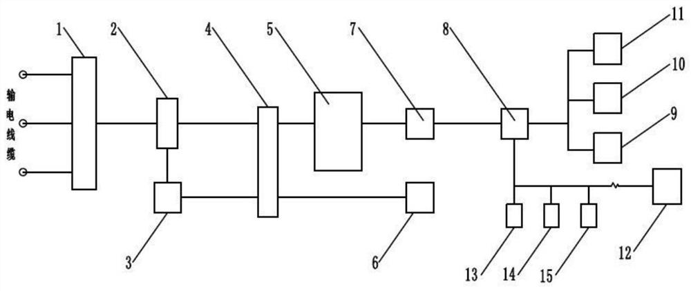
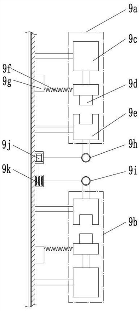
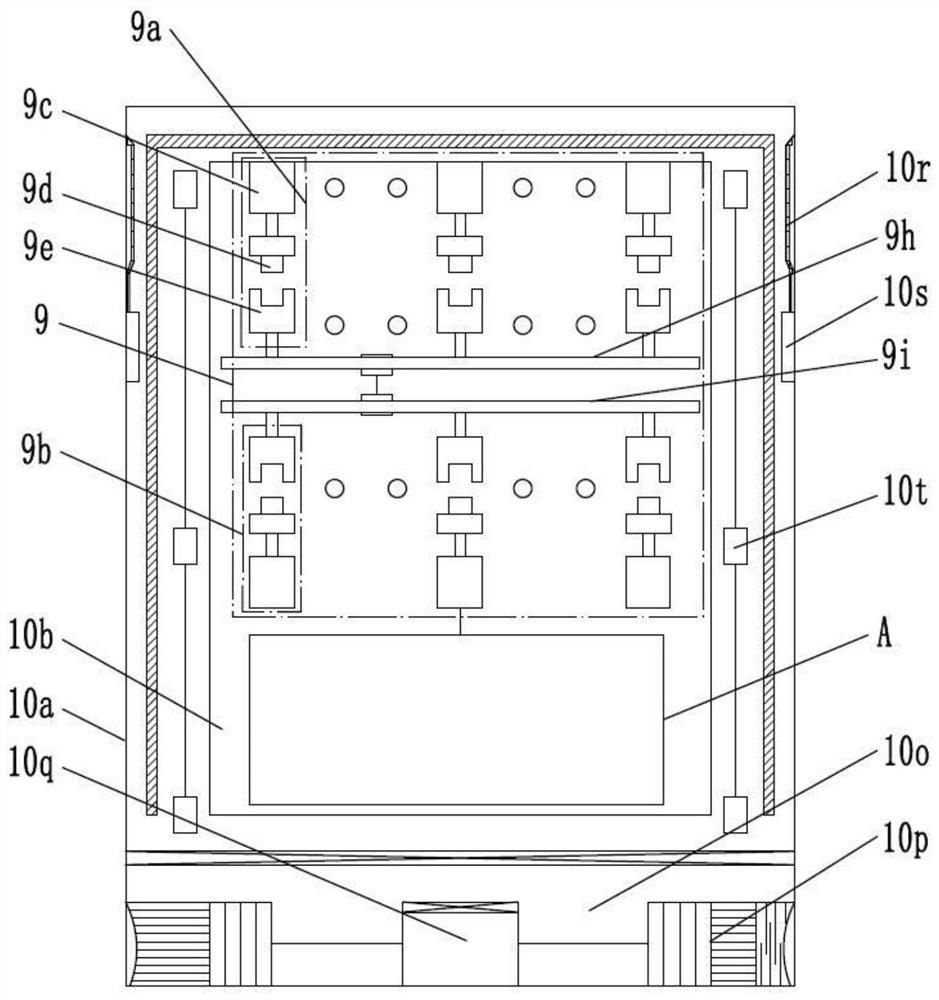
[0020] as attached Figure 1~6 The shown power transmission bus system suitable for high altitude areas includes collector 1, signal processor 2, filter unit 2, signal conversion unit 3, signal monitoring unit 4, central processing unit 5, signal correction unit 6, signal Stabilization unit 7, signal output unit 8, circuit switching switch 9, dynamic harmonic correction device 10, reactive power compensation device 11, the collector 1 is sequentially connected to the filter unit 2, signal conversion unit 3, signal monitoring unit 4, central A processor unit 5, a signal correction unit 6, a signal stabilization unit 7, and a signal output unit 8, the filtering unit 2 is sequentiall...


PUM


Abstract

The invention discloses an electric energy transmission bus system suitable for high-altitude areas, including a collector, a signal processor, a filter unit, a signal conversion unit, a signal monitoring unit, a central processing unit, a signal correction unit, a signal stabilization unit and a signal Output unit, circuit switching switch, dynamic harmonic correction device, reactive power compensation device. The invention can reasonably configure the power grid, adaptively perform active or reactive power compensation, reduce the loss of the power grid, improve the transmission quality of the power grid, ensure the continuity and stability of power transmission, and avoid the waste of electric energy; solve the inconvenience of transportation in plateau areas , the geographical environment is complex, which brings great difficulties to maintenance and high maintenance costs. It can also realize intelligent supervision control and configuration of power transmission, effectively promote the automation and intelligent management of reactive power compensation devices, and achieve energy saving. The purpose of reducing consumption and improving the economic benefits of power transmission.

Description

technical field [0001] The invention belongs to the technical field of plateau power transmission equipment, and in particular relates to a power transmission busbar system suitable for high-altitude regions with stable voltage and reduced power loss. Background technique [0002] In the power system, especially the power system in the plateau area, in the medium and long-distance transmission, the transmission distance is long, the number of step-down layers is large, and the operation status is greatly affected by the operation mode and power load changes. The corresponding distribution lines The absorbed reactive power is also different, which will cause excessive voltage fluctuations, and there are problems such as overvoltage and harmonics. In different regions and different time periods, the power load of each distribution line in the distribution network is different, and the voltage of the circuit will increase or decrease according to the load. In this case, if no r...

Claims


Application Information

Patent Timeline
Patent Type & Authority Patents(China)
IPC IPC(8): H02J13/00H02J3/16H02J3/01H02B1/28H02B1/56H02B1/30
CPCH02J13/0075H02J3/16H02J3/01H02B1/28H02B1/565H02B1/30Y04S10/22Y04S40/124Y04S40/126Y02E40/30Y02E40/40Y02E40/70Y02E60/00
Inventor 陈迪邹歆姚策益马联超冉峻梅
Owner 昆明东控电器成套设备有限公司
Why Eureka
Try Eureka