DC power supply and distribution structure

A power distribution structure and DC power supply technology, which is applied in the substation/power distribution device shell, emergency protection circuit device for limiting overcurrent/overvoltage, electric light source, etc., can solve the problem of inability to adjust brightness and color temperature, and load interval control , line stop working and other problems, to achieve the effect of improving system intelligence, reliability and safety level

Pending Publication Date: 2019-08-23
马化盛
View PDF0 Cites 2 Cited by
  • Summary
  • Abstract
  • Description
  • Claims
  • Application Information

AI Technical Summary

Problems solved by technology

[0002] The first generation of centralized DC power supply technology for ordinary street lamps is to centrally rectify the AC mains power through a rectifier and then output a controllable unipolar DC power (about 200-300V) isolated from the mains power and the earth to supply the DC load. This is the basic DC power supply. Centralized power supply lines; when a serious fault occurs on a single-pole line, such as line short circuit, power supply damage, etc., it is easy to cause the entire line to stop working, and all loads on the line stop working, which is not allowed in public lighting scenarios such as roads and subway stations; Shared lines cannot control loads at intervals, such as switching lights at odd and even intervals; due to shared lines, brightness and color temperature cannot be adjusted at the same time by adjusting DC voltage; 200-300V DC does not belong to the category of safe voltage, and safety needs to be improved

Method used


Image

  • DC power supply and distribution structure
  • DC power supply and distribution structure

Examples


Embodiment Construction

[0021] The present invention will be further described in detail below in conjunction with the embodiments and the accompanying drawings, but the embodiments of the present invention are not limited thereto.

[0022] Concrete implementation process of the present invention is as follows:

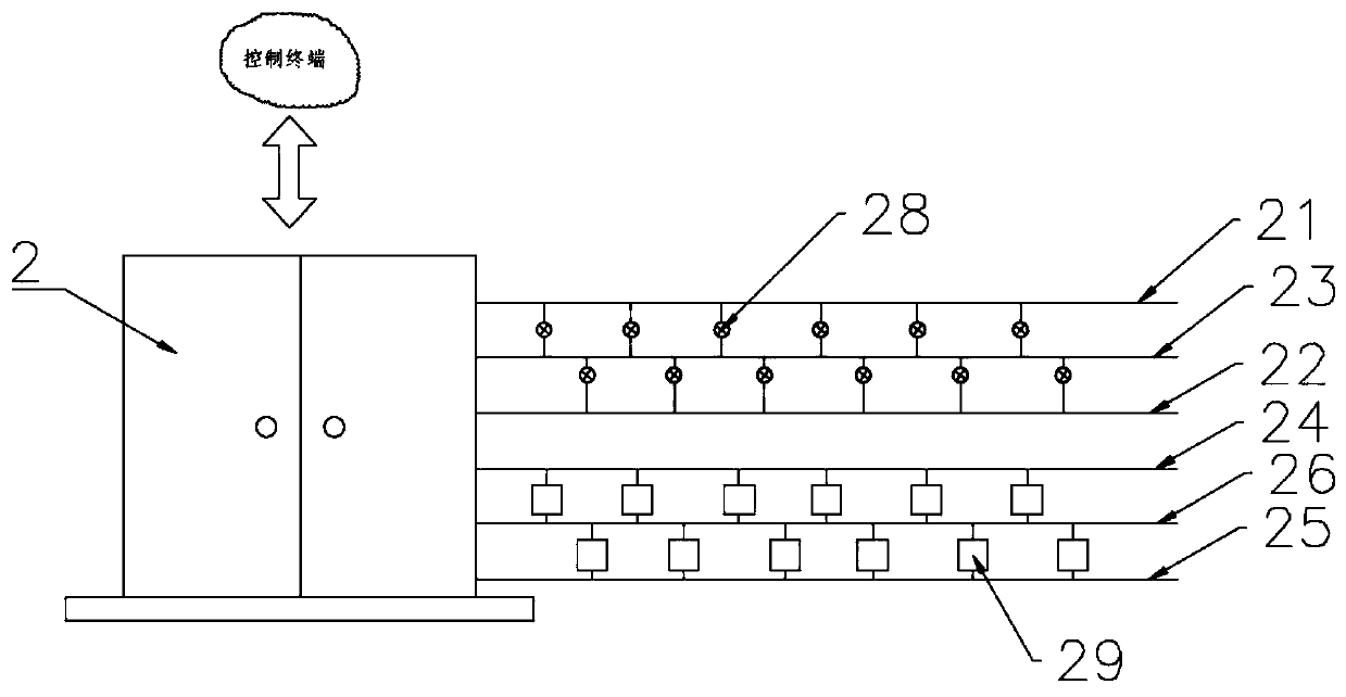
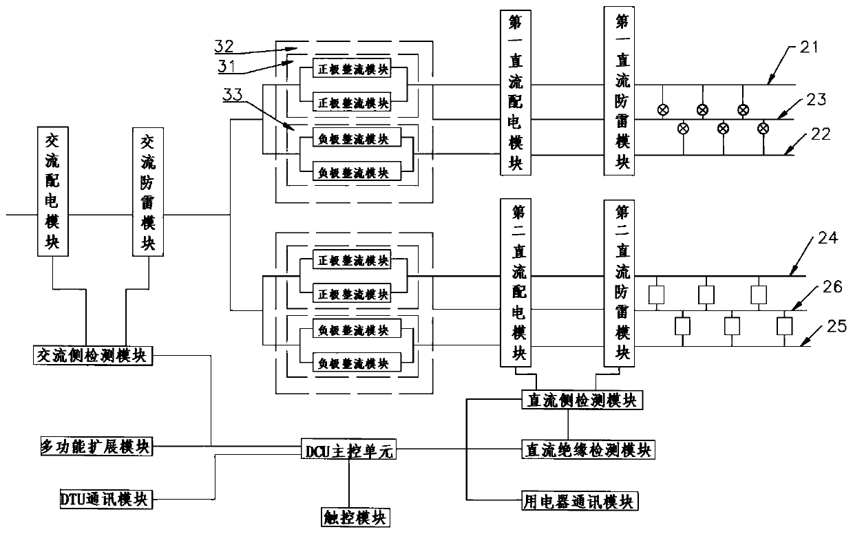
[0023] Such as Figure 1 to Figure 2 As shown, a DC power supply distribution structure includes: a control terminal, a DC cabinet 2, a bipolar DC busbar and a DC electrical appliance, the bipolar DC busbar includes a DC positive line, a DC neutral line and a DC negative line. The DC electrical appliance is connected between the DC positive line and the DC neutral line and between the DC negative line and the DC neutral line. The DC positive line, DC negative line and DC neutral line are connected to the DC cabinet 2, and the DC cabinet 2 is connected to the market Electrically connected, the control terminal is connected to the DC cabinet 2 for signals. According to actual needs, DC elect...


PUM


Abstract

The invention relates to the technical field of power supply and distribution, in particular to a DC power supply and distribution structure. The structure comprises a control terminal, a DC cabinet,a bipolar DC bus and DC electric appliances, and the bipolar DC bus comprises a DC positive line, a DC neutral line and a DC negative line. The DC electric appliances are connected between the DC positive line and the DC neutral line, between the DC negative line and the DC neutral line and between the DC positive line and the DC negative line, wherein the DC positive line, the DC negative line and the DC neutral line are connected to the DC cabinet, and the control terminal is in signal connection with the DC cabinet. A two-pole three-wire system DC bus is adopted in the invention, and loadsare symmetrically arranged, so the voltage drop of the DC neutral line can reach zero at the minimum, the transmission distance is equivalent to that of a single-pole voltage-doubling two-wire system,and the engineering adaptability is extremely high, that is, the power supply voltage of an electric appliance is low, and electricity utilization is safer; the positive and negative poles of the DCelectric appliances are arranged in a staggered mode, thereby achieving the double-bus mutual backup, and avoiding the serious consequence that an existing single-bus scheme has a single-bus fault, and consequently all-road-section lamp turning-off is likely to happen.

Description

technical field [0001] The invention relates to the technical field of power supply and distribution, in particular to a DC power supply and distribution structure. Background technique [0002] The first generation of centralized DC power supply technology for ordinary street lamps is to centrally rectify the AC mains power through a rectifier and then output a controllable unipolar DC power (about 200-300V) isolated from the mains power and the earth to supply the DC load. This is the basic DC power supply. Centralized power supply lines; when a serious fault occurs on a single-pole line, such as line short circuit, power supply damage, etc., it is easy to cause the entire line to stop working, and all loads on the line stop working, which is not allowed in public lighting scenarios such as roads and subway stations; Shared lines cannot control loads at intervals, such as switching lights at odd and even intervals; because of shared lines, brightness and color temperature ...

Claims


Application Information

Patent Timeline
Patent Type & Authority Applications(China)
IPC IPC(8): H05B33/08H02B1/30H02M7/02H02H9/04H05B44/00
CPCH02B1/30H02M7/02H02H9/04H05B45/37H05B45/10Y02B20/30
Inventor 马化盛
Owner 马化盛
Why Eureka
Try Eureka