Flight ranging system and correction method

A technology of ranging system and correction method, applied in the field of time-of-flight ranging system and correction that can avoid offset, and can solve problems such as interval-time interval and the like

Active Publication Date: 2019-08-23
SHENZHEN GOODIX TECH CO LTD
View PDF12 Cites 6 Cited by
  • Summary
  • Abstract
  • Description
  • Claims
  • Application Information

AI Technical Summary

Problems solved by technology

However, the existing time-of-flight ranging system has many non-idealities. For example, the two conduction times of the two transmission gates (Transmission Gate) in the photosensitive pixel circuit used for time-of-flight ranging must be separated by a time interval, or the transmission The pulse to the light-emitting unit may be a non-ideal continuous square wave, resulting in an offset between the measured distance calculated by the time-of-flight distance measurement method and the actual distance (Offset)

Method used


Image

  • Flight ranging system and correction method
  • Flight ranging system and correction method
  • Flight ranging system and correction method

Examples


Embodiment Construction

[0021] In order to make the purpose, technical solutions and advantages of the present application more clearly understood, the present application will be described in further detail below with reference to the accompanying drawings and embodiments. It should be understood that the specific embodiments described herein are only used to explain the present application, but not to limit the present application.

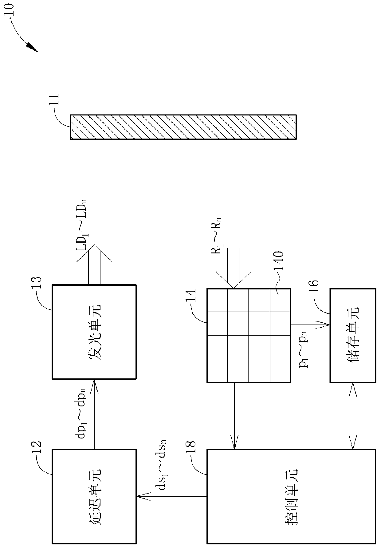
[0022] Please refer to figure 1 , figure 1 It is a schematic diagram of the time-of-flight ranging system 10 according to the embodiment of the present application. The time-of-flight ranging system 10 includes a delay unit 12 , a light-emitting unit 13 , a photosensitive pixel array 14 , a storage unit 16 and a control unit 18 . In the calibration stage of the time-of-flight ranging system 10, the reflector 11 is set at a known fixed distance GD from the time-of-flight ranging system 10, and the light-emitting unit 13 emits light toward the reflector 11 to sense the ...


PUM


Abstract

A flight ranging system (10) comprises a delay unit (12), which is used to generate a plurality of delay pulses according to a plurality of delay signals, wherein the delay signals are corresponding to multiple delay periods; a light emitting unit (13), which is used to generate a plurality of delay pulse light according to a plurality of delay pulses; a photosensitive pixel circuit (14), which receives the delay reflected light and generates a plurality of pixel signals; a storage unit (16), which is used to store the corresponding relationship between the multiple delay periods and the pixelsignals; and a control unit (18) for generating a plurality of delay signals. The flight ranging system (10) carry out flight ranging according to the corresponding relationship between the multipledelay periods and the pixel signals. The invention also relates to a correction method for the flight ranging system and a flight ranging method.

Description

technical field [0001] The present application relates to a time-of-flight ranging system and a calibration method, and in particular, to a time-of-flight ranging system and a calibration method that can avoid offsets. Background technique [0002] With the rapid development of science and technology, the acquisition of three-dimensional information of objects has broad application prospects in many application fields, such as production automation, human-computer interaction, medical diagnosis, reverse engineering, digital modeling, etc. Among them, the structured light three-dimensional measurement method, as a non-contact three-dimensional information acquisition technology, has been widely used because of its advantages of simple implementation, high speed and high precision. [0003] Time of Flight (ToF) ranging method is a commonly used three-dimensional depth measurement method. However, the existing time-of-flight ranging system has many non-idealities. For example,...

Claims


Application Information

Patent Timeline
Patent Type & Authority Applications(China)
IPC IPC(8): G01S7/497G01S17/10G01S7/4865G01S7/4863G01S17/89G01S17/894
CPCG01S7/497G01S17/10G01S7/4863G01S7/4865G01S17/894G01C3/08G01S17/36G01S17/89
Inventor 阙圣峻
Owner SHENZHEN GOODIX TECH CO LTD
Why Eureka
Try Eureka