Underground water well pump room air convection system

An air convection and pump room technology, applied in the direction of pumps, pump devices, pump components, etc., can solve the problems of easy mutual interference of air flow, insufficient air flow, and insufficient air flow distance, so as to avoid excessive contact and interference and improve heat dissipation effect, smooth flow effect

Pending Publication Date: 2019-08-27
湖南达道新能源开发有限公司
View PDF7 Cites 0 Cited by
  • Summary
  • Abstract
  • Description
  • Claims
  • Application Information

AI Technical Summary

Problems solved by technology

[0003] The pump room can be effectively cooled by ventilation. At present, mechanical air supply and mechanical exhaust are generally used to increase air convection in the pump room. When the pump room is mechanically blown, the airflow is sent into the pump in a straight line. In the pump room, the distance of air delivery is not enough, and because the air flow is easy to interfere with each other in the pump room, the air circulation is not smooth enough

Method used


Image

  • Underground water well pump room air convection system
  • Underground water well pump room air convection system
  • Underground water well pump room air convection system

Examples


Embodiment Construction

[0020] The present invention will be further described below in conjunction with the accompanying drawings and embodiments.

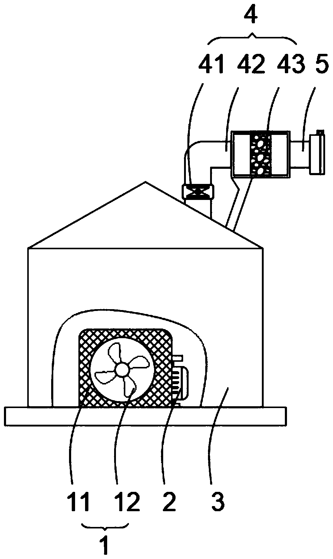
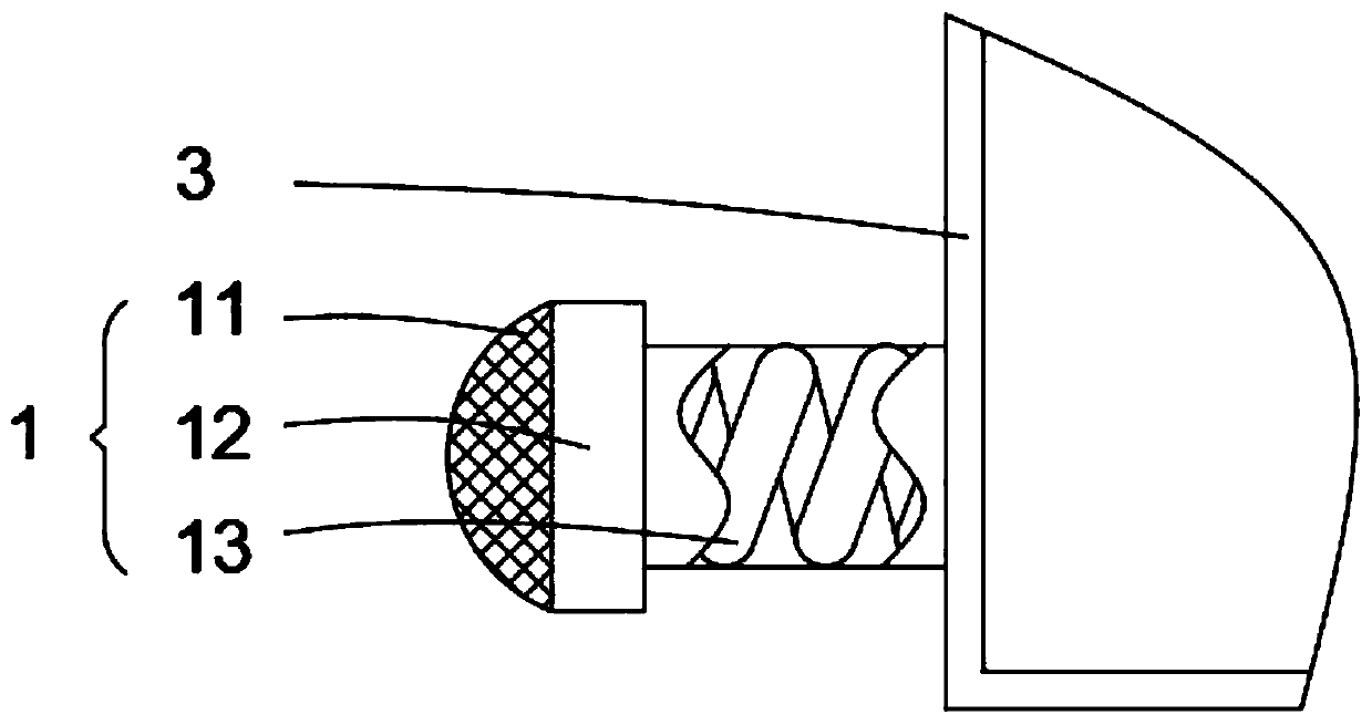
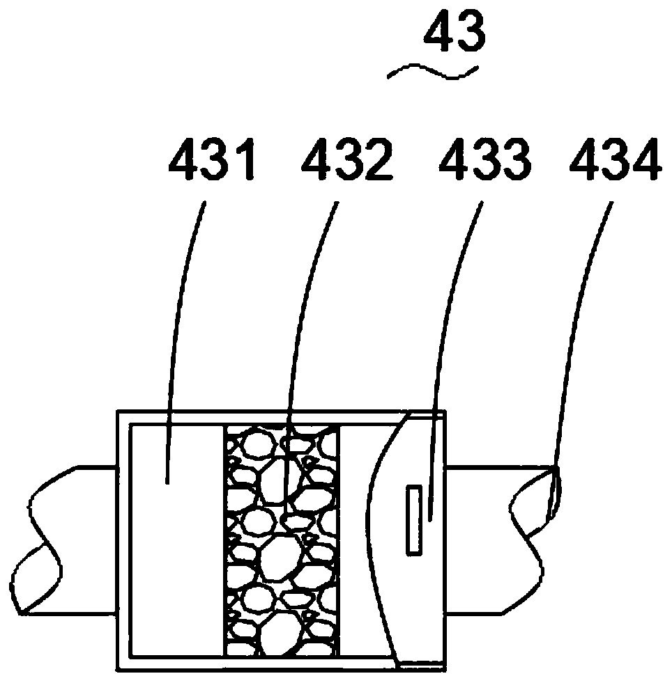
[0021] Please refer to figure 1 , figure 2 , image 3 and Figure 4 ,in, figure 1 A schematic structural view of a preferred embodiment of the air convection system of the groundwater well pump room provided by the present invention; figure 2 figure 1 The schematic diagram of the installation structure of the intake mechanism shown; image 3 for figure 1 The structural schematic diagram of the deodorization structure shown; Figure 4 for figure 1 Schematic diagram of the structure of the movable door mechanism shown. The air convection system of the groundwater well pump room includes: a pump room 3, in which a water pump 2 is installed; an air intake mechanism 1, which communicates with the air inlet at the bottom of the pump room 3, and the air inlet at the bottom of the pump room 3 It is arranged in alignment with the water pump 2; the ex...


PUM


Abstract

The invention provides an underground water well pump room air convection system. The underground water well pump room air convection system comprises a pump room, an air inlet mechanism, an exhaust mechanism and a movable door mechanism, wherein a water pump is arranged in the pump room; the air inlet mechanism is in communication an air inlet at the bottom of the pump room, and the air inlet atthe bottom of the pump room is aligned with the water pump; the air inlet mechanism is mainly composed of a filter cover, an air inlet fan and an air inlet pipe; one end of the air inlet pipe is in communication the air inlet in the bottom of the pump room, one end of the air inlet pipe is connected with a filter cover, a spiral air channel is formed in the air inlet pipe, and spiral air inlet isformed in the pump room; the exhaust mechanism is in communication an exhaust port at the bottom of the pump room; and the movable door mechanism is arranged at an air outlet of the exhaust mechanism.The underground water well pump room air convection system has the advantage of spiral air inlet.

Description

technical field [0001] The invention relates to the field of water pumping room facilities, in particular to an air convection system for a groundwater well pumping room. Background technique [0002] In the pump room, the power equipment will generate a lot of heat during operation. In the pump room with poor heat dissipation, the temperature in the plant will rise quickly. High temperature not only affects the working environment of the staff, but more importantly, affects the health of the staff; at the same time, it is more serious to accelerate the aging of the motor insulation, reduce the efficiency, and cause the failure of electrical equipment. Under normal conditions, every time the temperature of the motor increases by 8C above the rated value, its service life will be reduced by 50%, and its power will be reduced by 25%. Therefore, the design of the pump room should pay great attention to cooling measures. [0003] The pump room can be effectively cooled by venti...

Claims


Application Information

Patent Timeline
Patent Type & Authority Applications(China)
IPC IPC(8): F04D29/58F04D25/08F04D29/70F04D29/52B01D53/04B01D46/24F16K1/20
CPCB01D46/24B01D53/04B01D2253/102F04D25/08F04D29/522F04D29/588F04D29/703F16K1/20
Inventor 杨胜伟
Owner 湖南达道新能源开发有限公司
Why Eureka
Try Eureka