
Slurry bed reactor and reaction system used for Fischer-Tropsch synthesis

A Fischer-Tropsch synthesis and reaction system technology, which is used in the preparation of liquid hydrocarbon mixtures, chemical instruments and methods, chemical/physical processes, etc. Improve the effect of gas-liquid-solid mixing

Pending Publication Date: 2019-08-30
YANKUANG ENERGY R&D CO LTD
View PDF6 Cites 2 Cited by
  • Summary
  • Abstract
  • Description
  • Claims
  • Application Information

AI Technical Summary

Problems solved by technology

However, this patent is not equipped with a pressure drop tube, so the generation of dead zones and hot spots at the bottom of the bed cannot be avoided

Method used


Image

  • Slurry bed reactor and reaction system used for Fischer-Tropsch synthesis
  • Slurry bed reactor and reaction system used for Fischer-Tropsch synthesis
  • Slurry bed reactor and reaction system used for Fischer-Tropsch synthesis

Examples


Embodiment 1

[0053] A slurry bed reactor for Fischer-Tropsch synthesis, its structure is as figure 1 As shown, it includes a reactor main body 1, a gas distributor 2 arranged at the bottom of the reactor main body 1, several groups of heat transfer devices 4 arranged in the reactor main body 1 and a downcomer 5 matched with the heat transfer device 4, two A liquid-solid separation device 6 is provided between the heat removal devices 4, and a gas-solid washing and separation device 7 is provided on the top of the reactor main body 1.

[0054] The reactor main body 1 is a vertical pressure vessel. A false bottom 3 is provided between the bottom head connected to the bottom of the reactor main body 1 and the gas distributor 2. The false bottom 3 is a circular partition and forms and reacts with the bottom head. The false bottom area 9 is isolated from each other, and the pressure charging pipe S9 and the balance pipe S10 are arranged between the false bottom area 9 and the outlet of the reac...

Embodiment 2

[0062] The slurry bed reaction system for Fischer-Tropsch synthesis is roughly the same as in Example 1, except that the flushing component in this embodiment is a gas flushing component, and the flushing wax collection tank and the flushing wax tank used are both high-pressure gas storage tank, and the flushing gas in the high-pressure gas storage tank is synthetic gas or inert gas.

Embodiment 3

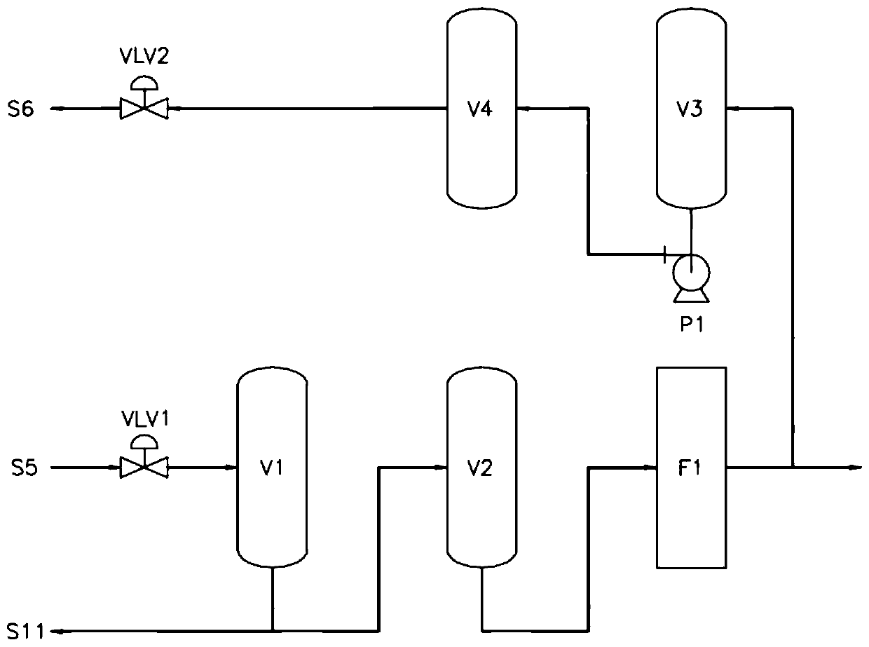
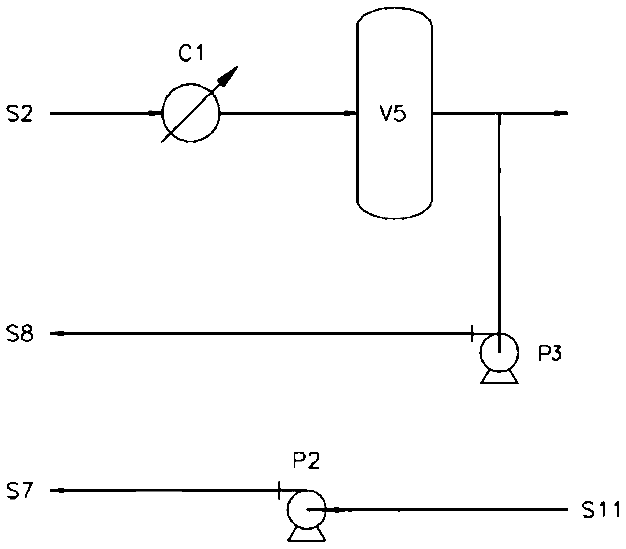
[0064] The technical solution in this embodiment includes figure 1 The slurry bed reactor shown, figure 2 filter-flush assembly shown and image 3 Wash components shown. The reactor has a tangential height of 45 m and an inner diameter of 0.52 m. Reaction zone 8 is filled with Fischer-Tropsch precipitated iron catalyst, and the gas volume of feed synthesis gas S1 is 320,000Nm 3 / h, where the ratio of hydrogen to carbon in the synthesis gas from the gas production unit is 2:1. The operating pressure of the reaction zone 8 is 2.3MPaG, and the operating temperature is 240°C. The output of Fischer-Tropsch wax is 4.8t / h, and the catalyst content in the mined Fischer-Tropsch wax S5 is 80ppm, and the catalyst content in the Fischer-Tropsch wax filtered out by filter F1 is <5ppm. The gas product condensate is 7.0t / h, and the catalyst content is <5ppm.


PUM


Abstract

The invention relates to a slurry bed reactor and a reaction system for Fischer-Tropsch synthesis. The reactor comprises: a reactor main body; a gas distributor arranged at the bottom part of the reactor main body; a plurality of groups of heat transfer devices arranged in the reactor main body, and downcomer pipes matching with the heat transfer devices, wherein a liquid-solid separation device is arranged between every two groups of heat transfer devices; and a gas-solid washing separation device arranged at the top part of the reactor. The reaction system comprises the reactor, and filtering-flushing assemblies and washing assemblies matching with the reactor. Compared with the prior art, the slurry bed reactor and the reaction system provided by the invention can realize industrial large-scale production of Fischer-Tropsch synthesis products, effectively increase the yield of a target product, and reduce the loss of a catalyst and the difficulty of separating the catalyst from a product.

Description

technical field [0001] The invention relates to a Fischer-Tropsch synthesis reactor, in particular to a slurry bed reactor and a reaction system for Fischer-Tropsch synthesis. Background technique [0002] Fischer-Tropsch Synthesis (FTS for short) is a method of converting synthesis gas (carbon monoxide and hydrogen) into Fischer-Tropsch products (mainly hydrocarbons, including alkyd acid) using Group VIII metal (such as iron, cobalt) catalysts. Catalyzed reactions of ketones, etc. The Fischer-Tropsch synthesis reactor is the key equipment of the Fischer-Tropsch synthesis process. At present, there are mainly two forms: fixed bed and slurry bed. Although the traditional fixed-bed reactor has a simple process, it is difficult to control the temperature, the catalyst is easy to carbonize, and the operation cost is high. The slurry bed reactor not only overcomes the above defects, but also has sufficient gas-liquid-solid three-phase mixing, excellent mass and heat transfer ef...

Claims


Application Information

Patent Timeline
IPC IPC(8): B01J8/22C10G2/00
CPCB01J8/22C10G2/344
Inventor 孙启文董良岳建平张宗森刘继森吴建民
Owner YANKUANG ENERGY R&D CO LTD
Learn More