Scale model testing device capable of simulating prototype pile foundation stress state

A test device and technology of stress state, which is applied in the test of foundation structure, foundation structure engineering, construction, etc., can solve the problem that the stress state of soil around the pile cannot be simulated.

Active Publication Date: 2019-08-30
HOHAI UNIV
View PDF6 Cites 3 Cited by
  • Summary
  • Abstract
  • Description
  • Claims
  • Application Information

AI Technical Summary

Problems solved by technology

[0004] The purpose of the present invention is to overcome the defect that the traditional scale model test cannot simulate the stress state of the soil around the pile, and provide a scaled model test device that can simulate the stress state of the prototype pile foundation and can be reused

Method used


Image

  • Scale model testing device capable of simulating prototype pile foundation stress state
  • Scale model testing device capable of simulating prototype pile foundation stress state
  • Scale model testing device capable of simulating prototype pile foundation stress state

Examples


Embodiment 1

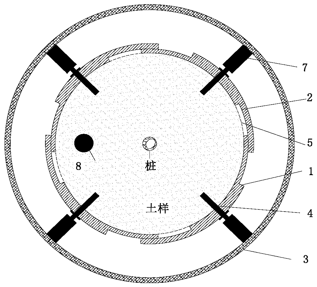
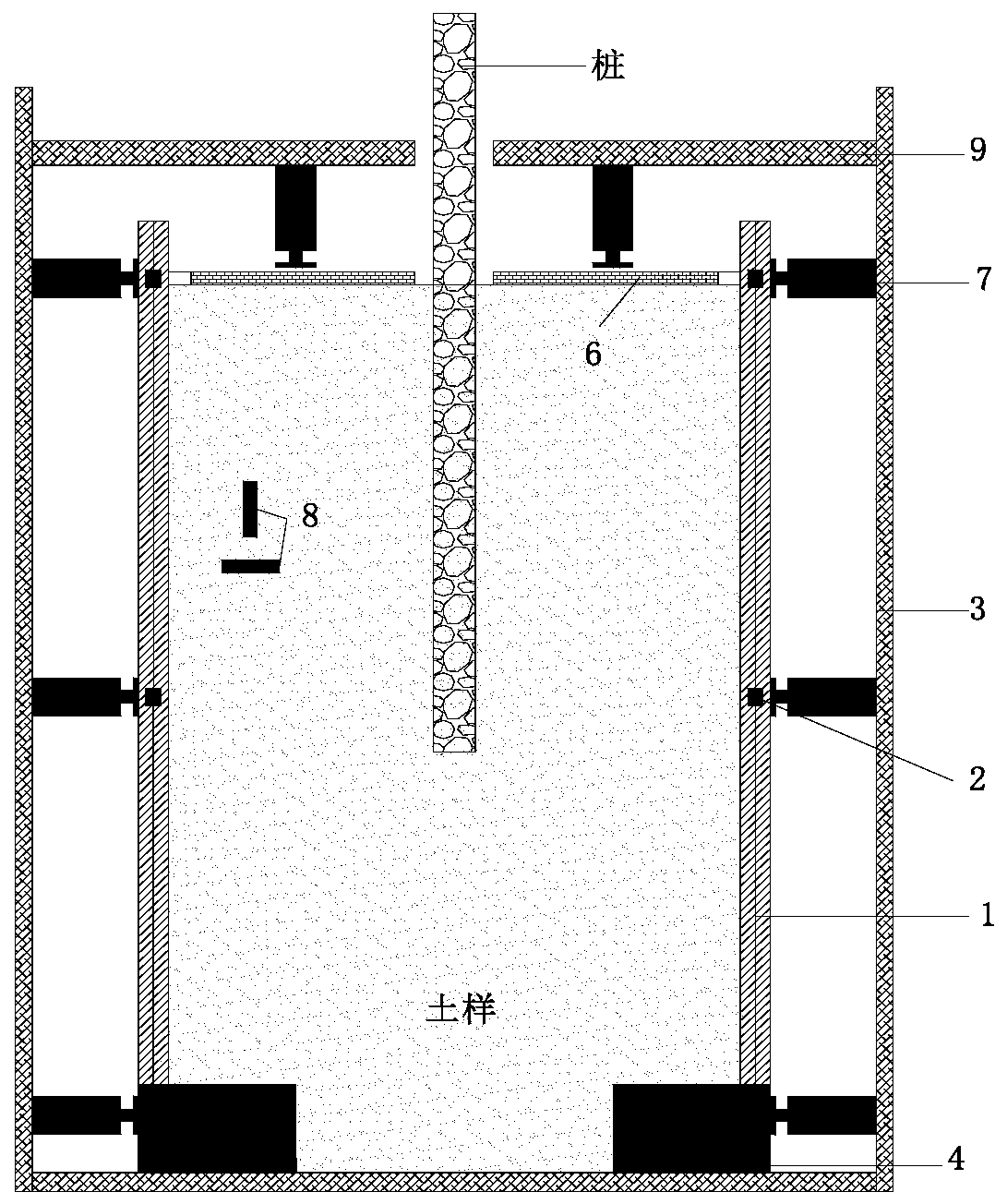
[0028] Such as Figure 1-4 , Figure 6 shows a scale model test device that can simulate the stress state of the prototype pile foundation. The test device includes a cylindrical outer box 3 and an inner box 1. The outer box is a shell structure with a bottom and no cover, and the inner box is arranged on the outer box. Inside, the soil sample is placed in the inner box, and the pile foundation is buried in the soil sample. There are many pairs of earth pressure gauges 8 arranged in the soil sample, and each pair of earth pressure gauges includes an earth pressure gauge parallel to the test pile foundation and an earth pressure gauge parallel to the test pile It is based on a vertical earth pressure gauge; the inner box is formed by at least four identical arc-shaped abrasive tools, and the bottom of the outer box is provided with four radial base rails 4, and the bottom of each abrasive tool is provided with a card slot 10, The card slot of each grinding tool is correspondin...

Embodiment 2

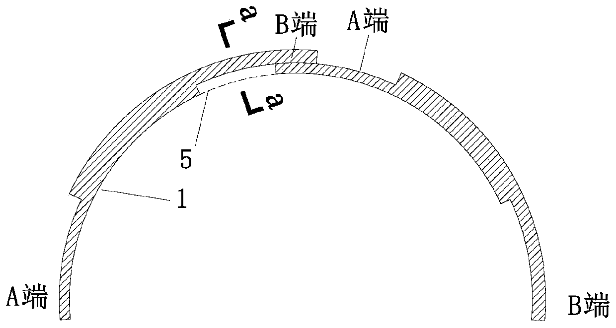
[0035] Such as Figure 5 The difference between this embodiment and Embodiment 1 is that a tenon 14 is provided on the outer wall of the end A of the abrasive tool, and a tenon groove 13 matching the tenon is provided on the inner wall of the end B of the abrasive tool, and the arc length of the tenon groove is along the B end of the abrasive tool. The direction is opened, and the free end of the tenon groove is provided with a baffle for preventing the tenon from slipping off.

Embodiment 3

[0037] Such as Figure 7 , 8 As shown, the difference between this embodiment and Embodiment 1 is that the device for applying pressure to the side wall of the inner box is a barrel-shaped air bag 16, and the pressure is applied to the side wall of the inner box by inflating the barrel-shaped air bag; pressure is applied to the top of the inner box The device is an annular air bag 15, which can apply pressure to the top of the inner box by inflating the annular air bag.

[0038] The side wall track in this embodiment can be the structure in embodiment 1 or embodiment 2.

[0039] In this embodiment, the earth pressure gauge 8 can also be replaced by a small pressure air bag to check changes in axial pressure and confining pressure in real time.

[0040] Concrete method of use of the present invention is as follows:

[0041] Place the outer box, set the bottom slot of a certain pair of abrasive tools on the outermost end of the base track at the bottom of the outer box, and set...


PUM


Abstract

The invention discloses a scale model testing device capable of simulating the prototype pile foundation stress state. The scale model testing device comprises a cylindrical outer box and inner box; asoil sample is placed in the inner box, and a pile foundation is buried in the soil sample; the inner box is defined by four or more identical circular-arc-shaped abrasive tools, and four radial baserails are arranged at the bottom of the outer box; a clamping groove of each abrasive tool is clamped in the corresponding base rail, and each abrasive tool and the two corresponding adjacent abrasive tools are connected in an end-to-end lapped mode; and a device applying the pressure to the side wall of the inner box is arranged between the outer box and the inner box, and thus the radial dimension of the inner box is decreased. By arranging the outer box and the retractable rigid inner box, the working property of a pile-soil system under the actual stress state is simulated in a segmentedmode, a vertical pressure gauge or an airbag is arranged in pile periphery soil to calibrate and real-timely monitor the pressure change of the pile-soil system, and thus the scale model testing device capable of being reutilized and simulating the stress state of the prototype pile-soil system is obtained.

Description

technical field [0001] The invention relates to a reduced-scale model test device capable of simulating the stress state of a prototype pile foundation, belonging to the field of indoor tests of geotechnical engineering. Background technique [0002] Soil is a smart material with "memory", and its mechanical properties are affected by the stress history. The same is true for the pile-soil interaction. Under the low stress state, the soil around the pile produces shear expansion, but under the high stress state, the soil around the pile produces shear shrinkage. [0003] The field test can restore the actual stress state of the pile-soil system, but the field soil layer is complex and changeable, not representative, and more importantly, the field test is very expensive and can only be used as a verification for other studies. Therefore, the experimental research on the mechanism of pile-soil interaction mainly relies on scaled-down model tests under constant stress. Howeve...

Claims


Application Information

Patent Timeline
Patent Type & Authority Applications(China)
IPC IPC(8): E02D33/00
CPCE02D33/00
Inventor 吕亚茹王媛苏静波于陶
Owner HOHAI UNIV
Why Eureka
Try Eureka