Visual physical simulation device under condition of complex hydrocarbon reservoir real core well network

A technology of physical simulation and real core, applied in wellbore/well components, production fluid, measurement, etc., can solve the problems of seepage under simulated well pattern conditions, difficulty in visual pressure monitoring, and inability to detect pressure, etc., to achieve convenient analysis and The effect of cognition, simple structure and low cost

Inactive Publication Date: 2014-07-23
XI'AN PETROLEUM UNIVERSITY
View PDF7 Cites 2 Cited by
  • Summary
  • Abstract
  • Description
  • Claims
  • Application Information

AI Technical Summary

Problems solved by technology

This kind of experiment is a physical simulation method widely used at present, and generally adopts linear or radial flow, which cannot simulate seepage under well pattern conditions. In addition, it is difficult to visualize this kind of physical simulation experiment; (2) Microscopic thin-section physical simulation, this technology adopts Real rock cores are made into thin slices, and the thin slices are used to study the law of permeability in the core under microscopic conditions, the mechanism of enhanced oil recovery, etc. This method can only be used for the equivalent simulation of the connection of multiple thin slices. It is possible to carry out displacement experiments in a single m

Method used


Image

  • Visual physical simulation device under condition of complex hydrocarbon reservoir real core well network
  • Visual physical simulation device under condition of complex hydrocarbon reservoir real core well network
  • Visual physical simulation device under condition of complex hydrocarbon reservoir real core well network

Examples


Embodiment Construction

[0024] The present invention is described in detail below in conjunction with accompanying drawing.

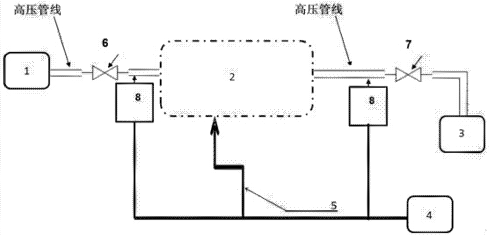
[0025] refer to figure 1 , the visual physical simulation device under real core well pattern conditions in complex oil and gas reservoirs, including the displacement system 1, the displacement system 1 is connected to the well pattern physical simulation unit 2 through the high-pressure pipeline and the first valve 6, and the well pattern physical simulation unit 2 passes through The high-pressure pipeline and the second valve 7 are connected to the flow metering system 3, and the same pressure sensor 8 is arranged on the high-pressure pipeline before and after the well pattern physical simulation unit 2, and the signal output ports of the two pressure sensors 8 are connected to the pressure of the monitoring system 4. The monitoring input is connected to the monitoring terminal. A microscope 5 is arranged above the well pattern physical simulation unit 2 , and the signal out...


PUM

PropertyMeasurementUnit
Thicknessaaaaaaaaaa
Heightaaaaaaaaaa

Abstract

Disclosed is a visual physical simulation device under the condition of a complex hydrocarbon reservoir real core well network. A displacement system is connected with a well network physical simulation unit. The well network physical simulation unit is connected with a flow metering system. A high pressure pipeline in front of the well network physical simulation unit and a high pressure pipeline behind the well network physical simulation unit are provided with identical pressure sensors respectively. The two pressure sensors are respectively connected with a monitoring system. A microscope is arranged above the well network physical simulation unit and connected with the monitoring system. The displacement system enables pressurized displacement fluid to enter the high pressure pipelines. The pressure sensors monitor pressure and then are connected into a real core set. Pressure at the preset position is monitored through the sensors and transmitted into the monitoring system. The displacement fluid enters a stainless steel tube groove and then flows into an exit end guiding groove. After the pressure is monitored by the rear-end pressure sensor, the displacement fluid flows to the metering system, and flow is recorded. The inlet end and the outlet end in the whole displacement process and signals of the pressure sensors of a well network physical simulation system are connected into the monitoring system. Meanwhile, the monitoring system monitors real-time images in the displacement process in real time through the microscope.

Description

technical field [0001] The invention belongs to the technical field of petroleum exploitation, and in particular relates to a visual physical simulation device under real core well pattern conditions of complex oil and gas reservoirs. Research on water flooding seepage law under various well patterns in oil and gas reservoir exploitation. Background technique [0002] It is very important to study the law of seepage in the process of oil and gas field exploitation. Unclear understanding of seepage law will seriously restrict the preparation of oil and gas field development plan and its development effect. If unreasonable well pattern or well row direction is adopted, it may cause premature water flooding of the oil field, and the water flooding sweep coefficient will be low, which will make the ultimate recovery On the low side, it is difficult to improve the development effect after later transformation. In addition, for the oilfields under development, before adjusting t...

Claims


Application Information

Patent Timeline
IPC IPC(8): E21B49/00E21B47/002E21B47/06E21B43/20
Inventor 张益陈军斌张明赵金省闫健
Owner XI'AN PETROLEUM UNIVERSITY
Why Eureka
Try Eureka