Tensioning device for MPCVD

A tensioning device and tensioning technology, applied in gaseous chemical plating, crystal growth, coating and other directions, can solve the problem of inability to measure and adjust the tensioning force of connecting rods in MPCVD equipment in time

Pending Publication Date: 2020-01-14
四川三三零半导体有限公司
View PDF0 Cites 2 Cited by
  • Summary
  • Abstract
  • Description
  • Claims
  • Application Information

AI Technical Summary

Problems solved by technology

[0005] Based on the above problems, the present invention provides a tensioning device for MPCVD, which is used to solve the problem that the tension of the connecting rod in the MPCVD equipment cannot be measured and adjusted in time in the prior art

Method used


Image

  • Tensioning device for MPCVD
  • Tensioning device for MPCVD
  • Tensioning device for MPCVD

Examples


Embodiment 1

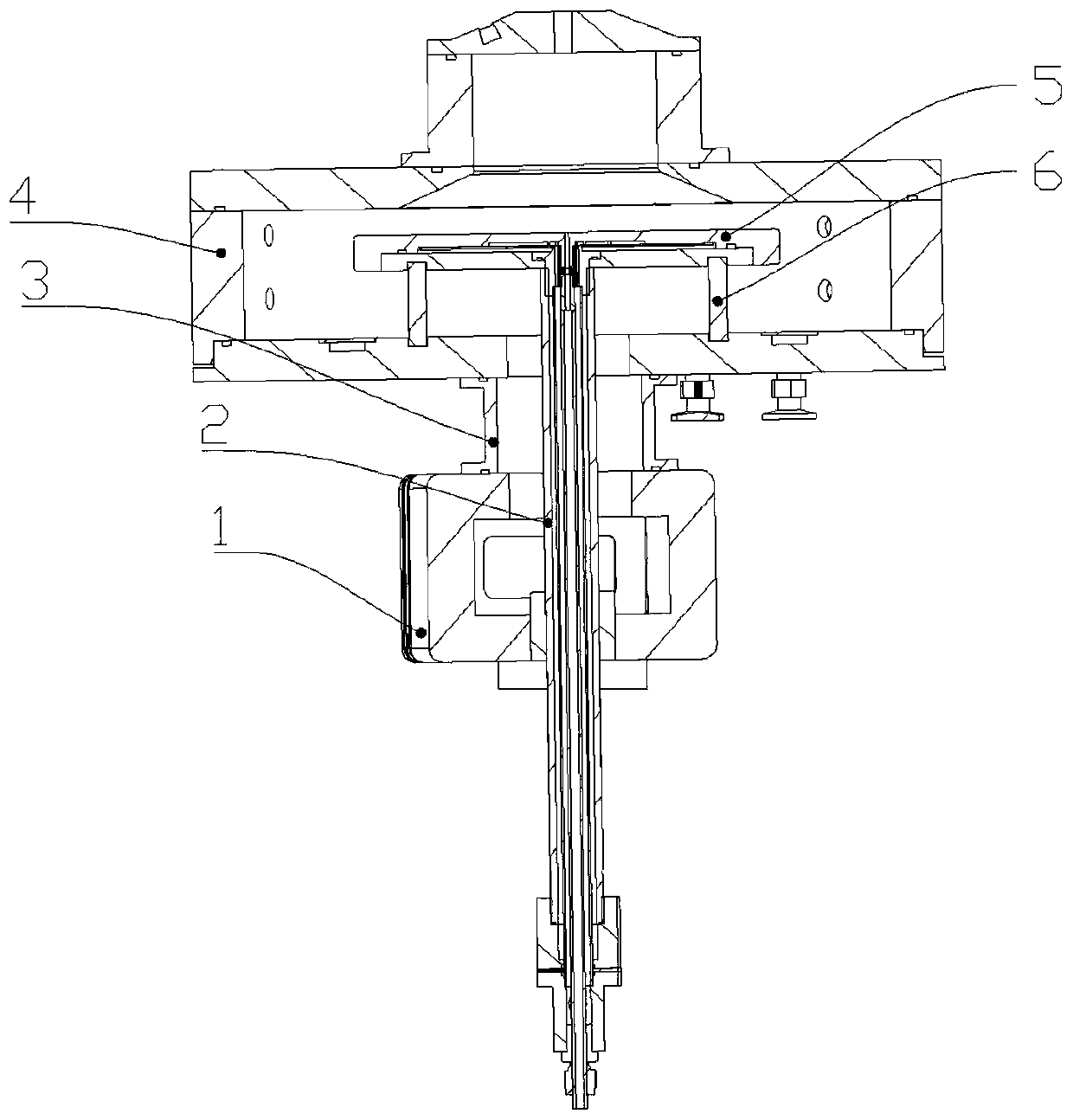
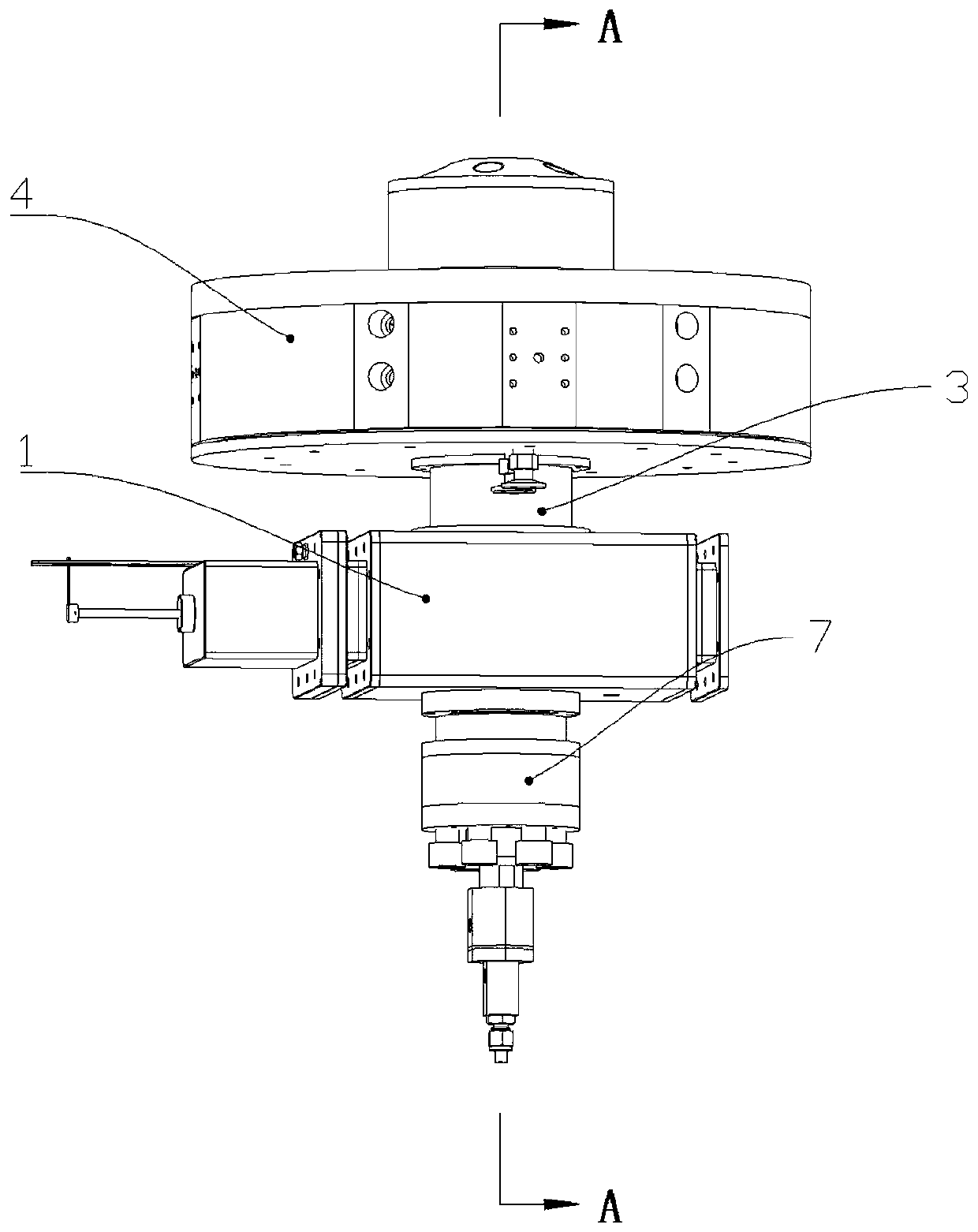
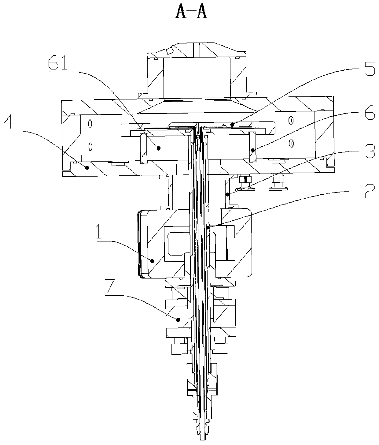
[0039] Such as Figure 2-6 As shown, a tensioning device for MPCVD includes a reaction cavity 4 and a waveguide cavity 1, the reaction cavity 4 and the waveguide cavity 1 are passed through by the same connecting rod 2, and the connecting rod 2 is also installed with a waveguide The tensioning device 7 below the cavity 1, the tensioning device 7 includes a tensioning assembly installed on the connecting rod 2, a plurality of pretensioning chambers 731 are opened in the tensioning assembly, each pretensioning chamber 731 is equipped with a The elastic element 77 in the vertical direction, the bottom surface of the tensioning assembly is equipped with a tray 72, and a plurality of pretensioning parts 71 corresponding to the elastic element 77 are installed on the tray 72, and the connecting rod 2 is also installed with the bottom surface of the tray 72. A tension member 78 is provided, and a load cell 75 is installed on the top surface of the tension assembly, and the load cell ...

Embodiment 2

[0044] Such as Figure 4-7 As shown, on the basis of Embodiment 1, this embodiment provides a more specific preferred structure of the tensioning device. That is, the tension assembly includes a tension disc 73 and a cover plate 74 , the cover plate 74 is installed on the top surface of the tension disc 73 , the tension disc 73 is installed on the top surface of the pallet 72 , and the elastic element 77 is in contact with the bottom surface of the cover plate 74 .

[0045] Preferably, the tray 72 is provided with a preloading hole 721 corresponding to the preloading chamber 731 one by one, the preloading member 71 is installed in the preloading hole 721 through threads, and an adjustment block 79 is also installed in the preloading chamber 731, and the elastic element 77 is installed on the adjustment block 79, and the pretensioner 71 is in contact with the adjustment block 79.

[0046] Preferably, the number of pretension chambers 731 is six, and the six pretension chambers...

Embodiment 3

[0051] Such as Figure 4-12 As shown, on the basis of Embodiment 1, this embodiment provides a more specific preferred structure of the tensioning device. That is, the connecting rod 2 is also equipped with a closing cover 76 positioned at the top surface of the load cell 75. The closing cover 76 extends into the reaction chamber 4. The closing cover 76 includes a closing plate 761 and a closing column 762 formed integrally with each other. The closing plate 761 is installed on the bottom surface of the waveguide cavity 1 , and the closing column 762 extends into the waveguide cavity 1 . The closing column 762 will have an interference fit with the waveguide cavity 1, the closing plate 761 can increase the contact area with the waveguide cavity 1, and the closing cover 76 can better seal the connection rod 2 and the waveguide cavity 1 .

[0052] The remaining parts are the same as those in Embodiment 1, so they will not be repeated here.


PUM


Abstract

The invention relates to the technical field of MPCVD equipment, in particular to a tensioning device for an MPCVD, and solves the problems of incapacity of timely measuring and adjusting of tensioning force of a connecting rod in MPCVD equipment in the prior art. The tensioning device comprises a reaction cavity, a waveguide cavity and a connecting rod, a tensioning device body located below thewaveguide cavity is further mounted on the connecting rod, the tensioning device body comprises a tensioning assembly, an elastic element, a pallet, a pre-tightened piece, a tensioning piece and a weighing sensor, and the weighing sensor is electrically connected to a display. According to the tensioning device for the MPCVD, as the change of the tensioning force of the elastic element is caused by the change of the tensioning force of the connecting rod, the expected force of the elastic element can be measured at any time through the weighing sensor in the tensioning device body and displayed on the display, the change of the tensioning force of the connecting rod can be viewed at any time through the display, and the change of the tensioning force of the connecting rod can be measured timely, so that the tensioning force of the connecting rod can be adjusted timely.

Description

technical field [0001] The invention relates to the technical field of MPCVD equipment, in particular to a tensioning device for MPCVD. Background technique [0002] Diamond has extremely high hardness and thermal conductivity, excellent optical transmission performance, high band gap and field emission characteristics and other extremely excellent properties, so it is widely used in optics, semiconductors, vacuum microelectronics, flat display, machinery and aviation, Aerospace and national defense and other fields have a very wide range of uses. The application in these fields will bring huge economic and social benefits to the development of high technology in the fields of national defense, electronics, optics and machinery. There are relatively few natural diamonds. In order to meet the demand, artificial diamond crystals are needed, and MPCVD equipment can be used to manufacture diamond crystals. [0003] Such as figure 1 As shown, the MPCVD equipment in the prior a...

Claims


Application Information

Patent Timeline
Patent Type & Authority Applications(China)
IPC IPC(8): C23C16/44C30B29/04
CPCC23C16/4409C30B29/04
Inventor 袁博刘虎陈实
Owner 四川三三零半导体有限公司
Why Eureka
Try Eureka