Integrated robot joint structure

A robot joint and integrated technology, which is applied in the direction of manipulators, electromechanical devices, mechanical equipment, etc., can solve the problems of complex debugging, high installation precision requirements, and large structural noise, and achieve the effects of reducing noise, reducing precision requirements, and reducing vibration

Active Publication Date: 2019-08-30
南通振康机械有限公司 +1
View PDF13 Cites 2 Cited by
  • Summary
  • Abstract
  • Description
  • Claims
  • Application Information

AI Technical Summary

Problems solved by technology

[0010] In order to overcome the problems of high noise, complex debugging and high installation precision requirements of the robot joint structure in the prior art, an integrated robot joint mechanism is provided, which is characterized in that it includes the output end body, the pin gear housing of the RV reducer, the fixed End body, integrated motor, output frame of RV reducer, eccentric shaft, planetary wheel, angular contact ball bearing, cycloidal wheel; the integrated motor includes a motor body and an input shaft connected to the motor, and the integrated motor Combined with the pin gear housing of the RV reducer to form an integrated unit, the pin gear housing of the RV reducer of the integrated unit is fixedly connected to the fixed end body, the output disc frame of the RV reducer is connected to the output end body, and the The eccentric shaft includes a cam, a concentric circle of the eccentric shaft, a tapered roller bearing and a needle roller cage. It is engaged with the pin gear housing for transmission, and there is a needle roller between the cycloid wheel and the pin gear housing. The angular contact ball bearings are arranged on both sides of the cycloid wheel and on the inner wall of the pin gear housing of the RV reducer. The outer ring of the angular contact ball bearing is clamped with the pin gear housing of the RV reducer, and the inner ring of the angular contact ball bearing is clamped with the output frame of the RV reducer

Method used


Image

  • Integrated robot joint structure
  • Integrated robot joint structure
  • Integrated robot joint structure

Examples


Embodiment 1

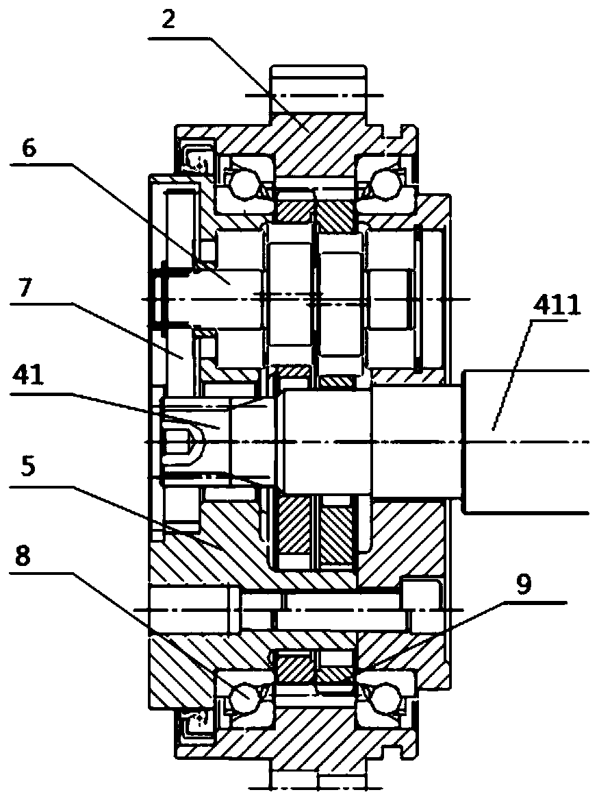
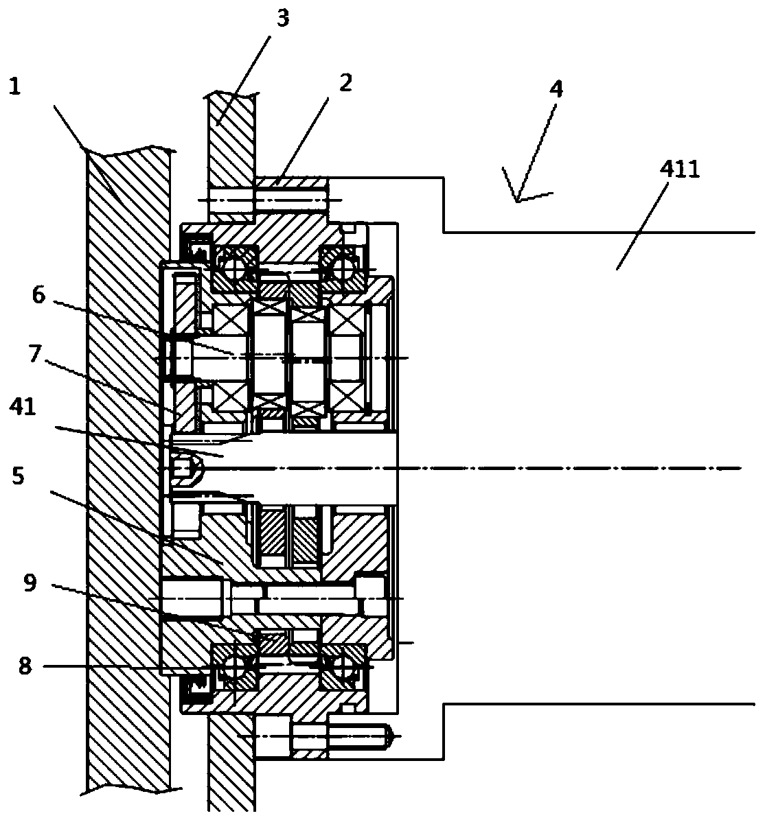
[0037] like figure 1 , figure 2 and image 3Shown: an integrated robot joint mechanism, characterized in that it includes the output body 1, the pin gear housing 2 of the RV reducer, the fixed end body 3, the integrated motor 4, the output frame 5 of the RV reducer, and the eccentric Shaft 6, planetary gear 7, angular contact ball bearing 8, cycloidal wheel 9; the integrated motor 4 includes the main body of the motor 411 and the input shaft 41 connected with the motor 411, the integrated motor 4 and the pin gear housing of the RV reducer 2 are combined into an integrated unit, the pin gear housing 2 of the RV reducer of the integrated unit is fixedly connected with the fixed end body 3, the output frame 5 of the RV reducer is connected with the output end body 1, and the eccentric shaft 6 includes a cam, concentric circles of the eccentric shaft, tapered roller bearings, and a needle roller cage. The cam of the eccentric shaft 6 is fitted with a needle roller cage bearing,...

Embodiment 2

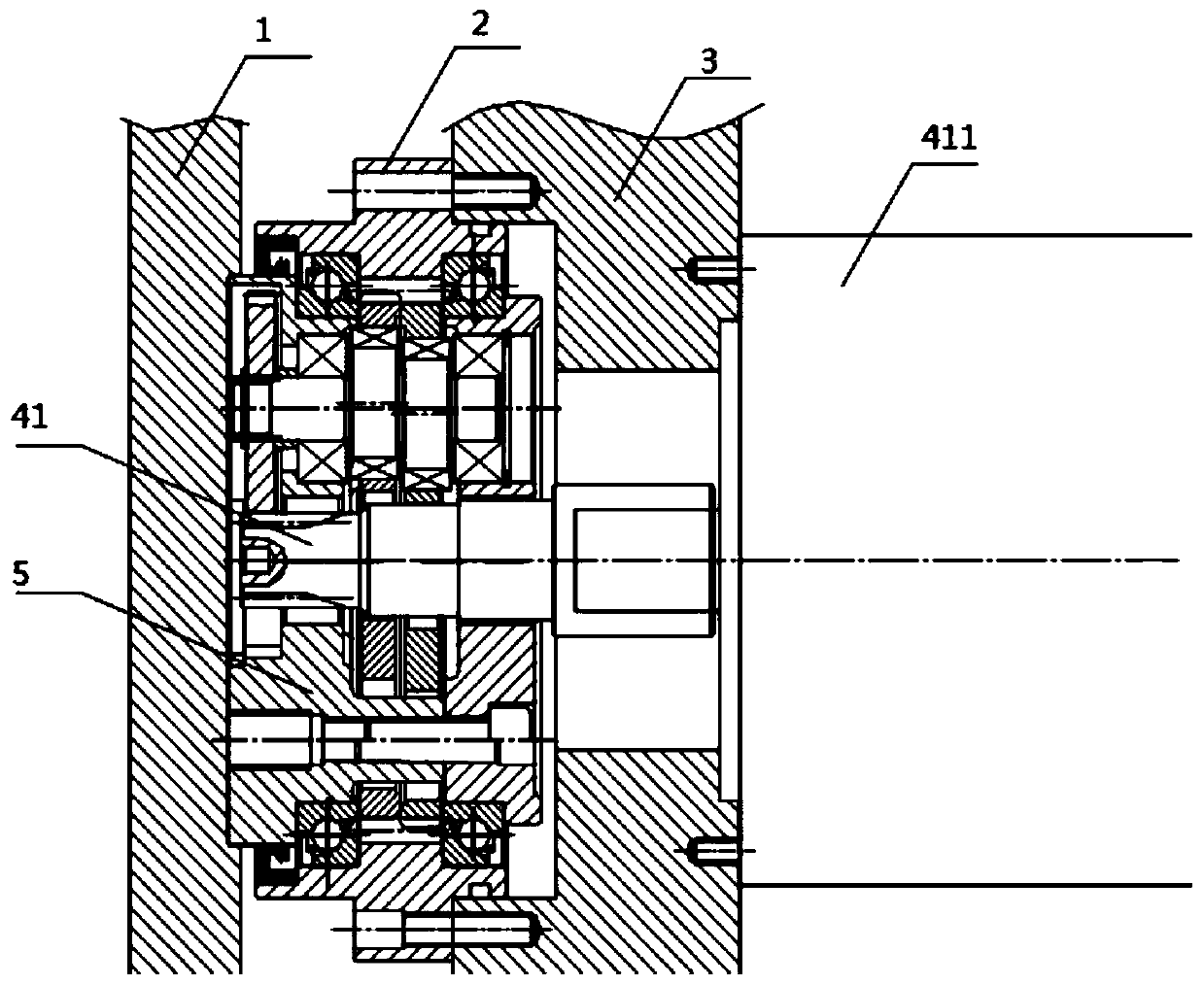
[0048] like figure 1 , figure 2 and Figure 4 Shown: an integrated robot joint mechanism, characterized in that it includes the output body 1, the pin gear housing 2 of the RV reducer, the fixed end body 3, the integrated motor 4, the output frame 5 of the RV reducer, and the eccentric Shaft 6, planetary gear 7, angular contact ball bearing 8, cycloidal wheel 9; the integrated motor 4 includes the main body of the motor 411 and the input shaft 41 connected with the motor 411, the integrated motor 4 and the pin gear housing of the RV reducer 2 are combined into an integrated unit, the pin gear housing 2 of the RV reducer of the integrated unit is fixedly connected with the fixed end body 3, the output frame 5 of the RV reducer is connected with the output end body 1, and the eccentric shaft 6 includes a cam, concentric circles of the eccentric shaft, tapered roller bearings, and a needle roller cage. The cam of the eccentric shaft 6 is fitted with a needle roller cage bearin...


PUM


Abstract

The invention provides an integrated robot joint mechanism. The integrated robot joint mechanism comprises an output end body, a pin gear shell of an RV reducer, a fixed end body, an integrated motor,an output disc frame of the RV reducer, an eccentric shaft, a planet wheel, an angular contact ball bearing and a cycloid wheel, wherein the integrated motor comprises a motor main body and an inputshaft connected with the motor; the integrated motor and an RV reducer pin gear shell are combined into an integrated unit; the pin gear shell of the RV reducer of the integrated unit is fixedly connected with the fixed end body; the output disc frame of the RV reducer is connected with the output end body; and the eccentric shaft comprises a cam, an eccentric shaft concentric circle, a tapered roller bearing and a needle roller retainer. In the technical field of RV speed reducers, the problems of large noise, complex debugging and high installation precision requirement of an existing robotjoint structure are solved by adopting the integrated robot joint mechanism.

Description

technical field [0001] The invention relates to the technical field of RV reducers, in particular to an integrated robot joint structure. Background technique [0002] RV reducer is a new type of reducer developed on the basis of cycloidal pinwheel transmission. There are two stages of deceleration structure: the first stage is a planetary deceleration structure, and the second stage is a cycloidal pinwheel deceleration structure. It has the advantages of high rigidity, high precision, high torque, and high transmission efficiency. It has smaller volume and greater overload capacity than the simple cycloid planetary transmission. In the transmission mechanism of Japanese robots, it has been used to a large extent Gradually replace the simple cycloid planetary transmission and harmonic transmission. [0003] figure 1 It is a schematic diagram of the structure of the RV reducer. Main components: pin gear housing 2, eccentric shaft 6, planetary gear 7, input shaft 41, outpu...

Claims


Application Information

Patent Timeline
IPC IPC(8): F16H1/32F16H57/023F16H57/02F16H57/029H02K7/116B25J17/00
CPCF16H1/32F16H57/023F16H57/02F16H57/029F16H57/0006H02K7/116B25J17/00F16H2001/323F16H2001/327F16H2057/02034F16H2057/02086
Inventor 顾京君顾磊江春峰
Owner 南通振康机械有限公司
Why Eureka
Try Eureka