
High-speed machining stability domain prediction method based on cutter tooth cutting time course fine integration

A technology of fine integration and prediction method, applied in the field of advanced manufacturing, which can solve problems such as low calculation accuracy and reduced calculation efficiency

Active Publication Date: 2019-08-30
NANJING UNIV OF AERONAUTICS & ASTRONAUTICS
View PDF3 Cites 6 Cited by
  • Summary
  • Abstract
  • Description
  • Claims
  • Application Information

AI Technical Summary

Problems solved by technology

[0004] The current patent application number is: "201510068454.7". When obtaining the stability lobe map, the transfer matrix needs m iterations at discrete intervals, which reduces the efficiency of calculation; the patent application number is: "2015100067259.2", which only uses nodes The above function values ​​are the same to fit the delay term, and the calculation accuracy is not high

Method used


Image

  • High-speed machining stability domain prediction method based on cutter tooth cutting time course fine integration
  • High-speed machining stability domain prediction method based on cutter tooth cutting time course fine integration
  • High-speed machining stability domain prediction method based on cutter tooth cutting time course fine integration

Examples


Embodiment Construction

[0118] The drawings constituting a part of the present invention are used to provide a further understanding of the present invention, and the schematic embodiments and descriptions of the present invention are used to explain the present invention, and do not constitute an improper limitation of the present invention.

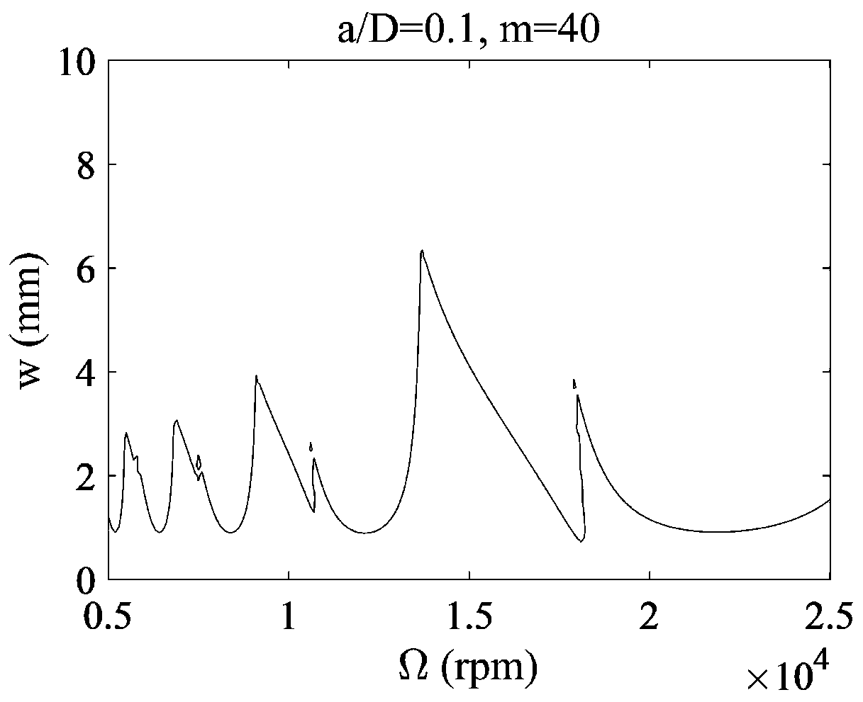
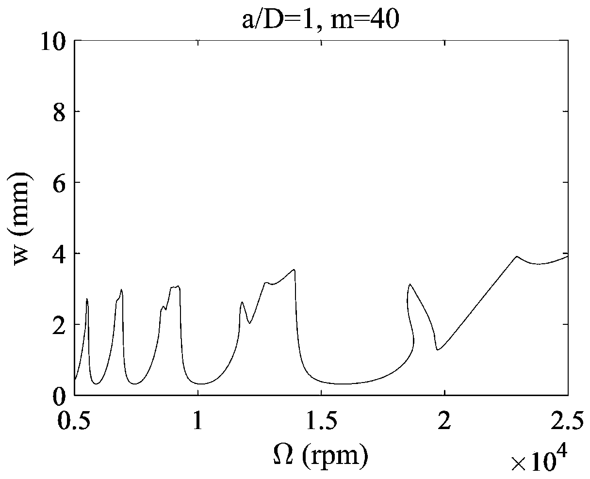
[0119] like figure 1 As shown, in this embodiment, the time-delay differential equation considering regenerative chatter milling dynamics is transformed into a space state form, and the space state equation of the time-delay differential equation is obtained; the spindle speed is discretized into K_n points, and the axial depth of cut Discrete into K_w points; Let R=0,1,2,...,K_n; Let J=0,1,2,...K_w; Divide the tooth cutting cycle of point (R, J) into several small intervals; Integrate and calculate the space state equation of the above-mentioned time-delay differential equation in any small interval of time to obtain the relationship equation between the stat...


PUM


Abstract

The invention provides a high-speed machining stability domain prediction method based on cutter tooth cutting time course fine integration. The high-speed machining stability domain prediction methodcomprises: firstly, establishing a high-speed milling dynamics model considering regeneration flutter; secondly, dispersing the rotation period of the main shaft, and simplifying the Duhamel integralin the time delay differential equation into an integral of a state item and a time delay item at each dispersed small interval; secondly, using a piecewise cubic Hermite interpolation polynomial tofit a time lag item, and meanwhile, using a plurality of known time node responses and derivatives thereof to approach a required item, so that the fitting error of a calculation method is reduced, and the precision of the prediction method is improved. In addition, in the process of solving the stable lobe graph, a fine integration algorithm is applied, matrix inversion operation in the calculation process is avoided, the time consumed by the calculation method is greatly shortened, and the calculation efficiency is improved.

Description

technical field [0001] The invention belongs to the field of advanced manufacturing technology, and in particular relates to a high-speed machining stable region prediction method based on fine integration of cutter tooth cutting time history. Background technique [0002] High-speed milling has the advantages of maintaining relatively low cutting force during machining, ensuring high machining accuracy and obtaining high material removal rate, and is widely used in the finishing fields of aviation, aerospace and automobile industry manufacturing. The realization of many advantages of high-speed milling is based on the realization of a vibration-free and stable cutting process under high-speed conditions. Due to the lack of systematic and effective theoretical guidance and practical tools for the control of high-speed cutting vibration and machining instability, most of the relevant enterprises still use experience or trial cutting methods to determine milling parameters whe...

Claims


Application Information

Patent Timeline
IPC IPC(8): G06F17/11G06F17/16
CPCG06F17/11G06F17/16
Inventor 杨文安黄超蔡旭林杨博郭宇廖文和林静明
Owner NANJING UNIV OF AERONAUTICS & ASTRONAUTICS
Learn More