Feeding and discharging plunger pump

A plunger pump, feeding and discharging technology, which is applied in the field of feeding and discharging plunger pumps, can solve the problems of short service life, extremely poor fluidity, and high temperature of the pump body, so as to increase the service life, reduce maintenance time, and reduce operation The effect of power consumption

Inactive Publication Date: 2019-09-03
青岛合能环境技术有限公司
View PDF2 Cites 2 Cited by
  • Summary
  • Abstract
  • Description
  • Claims
  • Application Information

AI Technical Summary

Problems solved by technology

[0008] The main purpose of the present invention is to provide a plunger pump for feeding and discharging materials to solve the problem of the traditional plunger pump in the prior art in the process of processing materials with large particle size, high impurity content, high solid content, and extremely poor fluidity. Problems such as clogging, high temperature of the pump body during work, difficult maintenance, and short service life of the pump body

Method used


Image

  • Feeding and discharging plunger pump
  • Feeding and discharging plunger pump
  • Feeding and discharging plunger pump

Examples


Embodiment 1

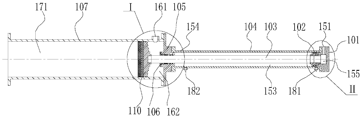
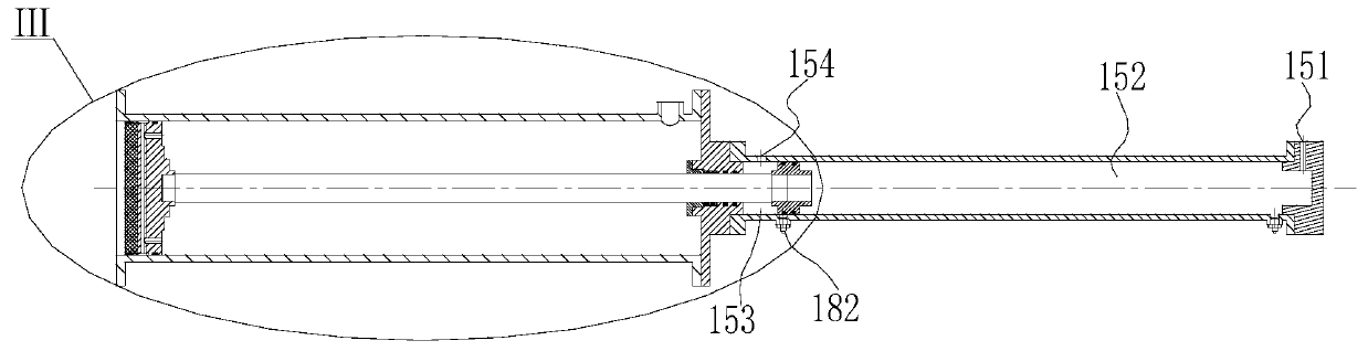
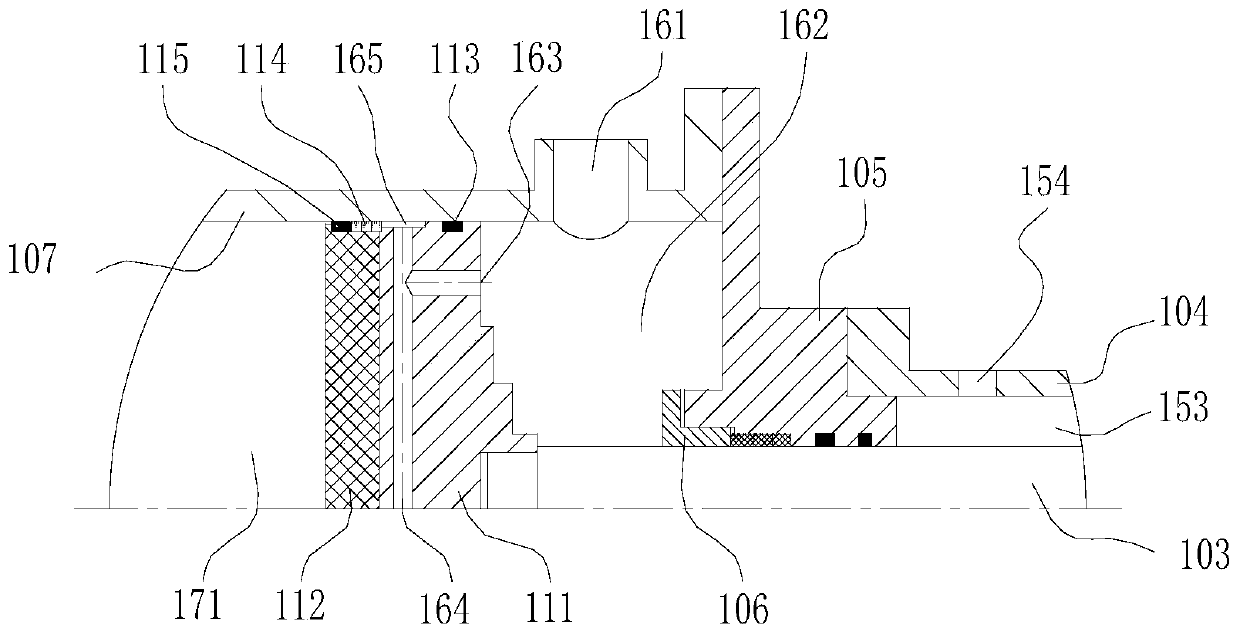
[0041] Such as Figure 1-5 As shown, the plunger pump device for feeding and discharging materials described in the present invention includes a hydraulic drive assembly and a material conveying assembly;

[0042]The hydraulic drive assembly includes a hydraulic cylinder block 104, a rear end cover 101, a hydraulic piston 102, and a piston rod 103. The inner cavity of the hydraulic cylinder block is installed in cooperation, and the front end of the side wall of the hydraulic cylinder block is provided with a front hydraulic oil filling port 154, and a groove 155 is provided on the end surface connecting the rear end cover with the internal cavity of the hydraulic cylinder block, and the groove passes through the rear hydraulic oil filling port 151 communicates with the outside.

[0043] The material conveying assembly includes a material cylinder 107 and a material piston 110, the material piston is installed at the front end of the piston rod, the material piston is located...

Embodiment 2

[0071] Such as Figure 6-8 As shown, the difference between this embodiment and embodiment 1 is:

[0072] The piston rod has a piston rod inner chamber 205, a water pipe 201 is installed in the piston rod inner chamber, a lock nut 203 and a guide sleeve 202 are installed at the front end of the water pipe, the outer wall of the guide sleeve has a seal, the end of the water pipe passes through the rear end cover, and is connected with the rear end cover. The end cover is fixedly connected, the water inlet hole is located at the center of the base, and the front end of the piston rod is connected to the water inlet hole; there is an annular groove 206 on the contact surface between the pressure bearing plate and the material cylinder, and the cut surface of the annular groove has a slope, close to the base The depth of the annular groove on one side is relatively deep, and the annular groove communicates with the annular water tank.

[0073] The outside of the water injection p...


PUM


Abstract

The invention relates to the field of pumps suitable for conveying special fluids, in particular to a feeding and discharging plunger pump. The feeding and discharging plunger pump comprises a hydraulic driving assembly and a material conveying assembly; the hydraulic driving assembly comprises a hydraulic cylinder body, a rear end cover, a hydraulic piston and a piston rod, wherein the rear end of the hydraulic cylinder body is connected with the rear end cover, the piston rod is positioned in the hydraulic cylinder body, the tail end of the piston rod is connected with a hydraulic piston, the hydraulic piston is matched with an inner cavity of the hydraulic cylinder body, and a front hydraulic oil injection port is formed in the front end of the side wall of the hydraulic cylinder body;and the material conveying assembly comprises a material cylinder body and a material piston, the material piston is arranged at the front end of the piston rod, the material piston is located in thematerial cylinder body, and a water injection port is formed in the tail end of the side wall of the material cylinder. According to the feeding and discharging plunger pump, the problems that in theprior art, a traditional plunger pump is large in particle size, high in impurity content, high in solid content and poor in liquidity, and in the working process, the temperature of a pump body is high, maintenance is difficult, and the service life of the pump body is short are solved.

Description

technical field [0001] The invention relates to the field of pumps suitable for conveying special fluids, in particular to a plunger pump for feeding and discharging materials. Background technique [0002] In recent years, with the continuous development of society, domestic kitchen waste generated by residential communities, catering centers, farmers' markets, and other municipal entrances has gradually increased. Relevant scientific researchers in my country have done a lot of introduction, absorption, exploration and improvement of domestic waste comprehensive treatment technology , such as dry anaerobic treatment of domestic waste technology as a new technology gradually entered the country and began to pilot construction in some cities. [0003] Although domestic waste classification has been vigorously called for and some results have been achieved in some pilot cities, overall, the organic part of domestic domestic kitchen waste used for anaerobic fermentation is stil...

Claims


Application Information

Patent Timeline
IPC IPC(8): F04B15/02F04B9/105F04B53/14F04B53/16F04B53/18F04B53/08
CPCF04B9/1076F04B15/02F04B53/08F04B53/14F04B53/162F04B53/18
Inventor 张培基姜鹏曲珍宽左文祥周添元晓蕾刘颖
Owner 青岛合能环境技术有限公司
Why Eureka
Try Eureka